AFL-xxA-N270 Series Panel PC
Page 38
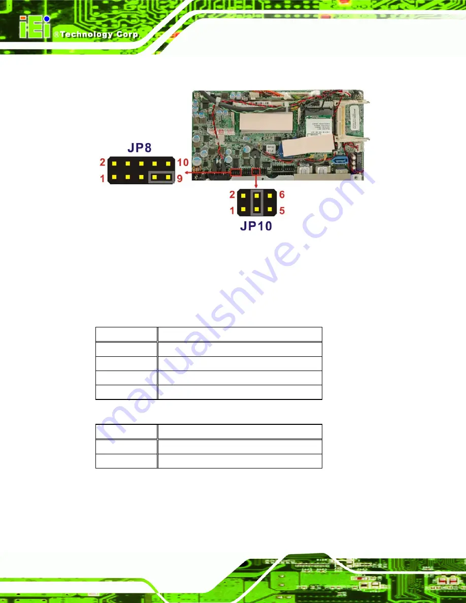
The COM1 and COM3 Pin 9 Setting jumper locations are shown in
Figure 4-8
below.
Figure 4-8: COM1 and COM3 Pin 9 Setting Jumper Locations
4.9.4.1 COM3 RS-422 and RS-485 Pinouts
The pinouts for RS-422 and RS-485 operation of external serial port COM 3 are detailed
below.
COM 3
RS-422 Description
Pin 1
TX-
Pin 2
TX+
Pin 6
RX-
Pin 7
RX+
Table 4-6: RS-422 Pinouts
COM 3
RS-485 Description
Pin 1
Data-
Pin 2
Data+
Table 4-7: RS-485 Pinouts
Summary of Contents for AFL-07A-N270/R/1G-R22
Page 15: ...AFL xxA N270 Series Panel PC Page 1 1 Introduction Chapter 1...
Page 23: ...AFL xxA N270 Series Panel PC Page 9 2 Detailed Specifications Chapter 2...
Page 36: ...AFL xxA N270 Series Panel PC Page 22 3 Unpacking Chapter 3...
Page 41: ...AFL xxA N270 Series Panel PC Page 27 4 Installation Chapter 4...
Page 70: ...AFL xxA N270 Series Panel PC Page 56 5 System Maintenance Chapter 5...
Page 77: ...AFL xxA N270 Series Panel PC Page 63 6 AMI BIOS Setup Chapter 6...
Page 117: ...AFL xxA N270 Series Panel PC Page 103 7 Software Drivers Chapter 7...
Page 145: ...AFL xxA N270 Series Panel PC Page 131 Step 1 A System Specifications Appendix A...
Page 149: ...AFL xxA N270 Series Panel PC Page 135 B Safety Precautions Appendix B...
Page 155: ...AFL xxA N270 Series Panel PC Page 141 C BIOS Configuration Options Appendix C...
Page 159: ...AFL xxA N270 Series Panel PC Page 145 D Watchdog Timer Appendix D...
Page 162: ...AFL xxA N270 Series Panel PC Page 148 E Hazardous Materials Disclosure Appendix E...
Page 166: ...AFL xxA N270 Series Panel PC Page 152 F Index...


