AFL-08B-N270 User Manual
Page 50
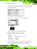
Table 2-13: RS-485 Pinouts
2.7.3 USB Device Connection
There are two external USB 2.0 connectors. To connect a USB 2.0 or USB 1.1 device,
please follow the instructions below.
Step 1:
Located the USB connectors
. The locations of the USB connectors are shown
in
Chapter 2
.
Step 2:
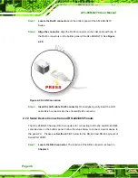
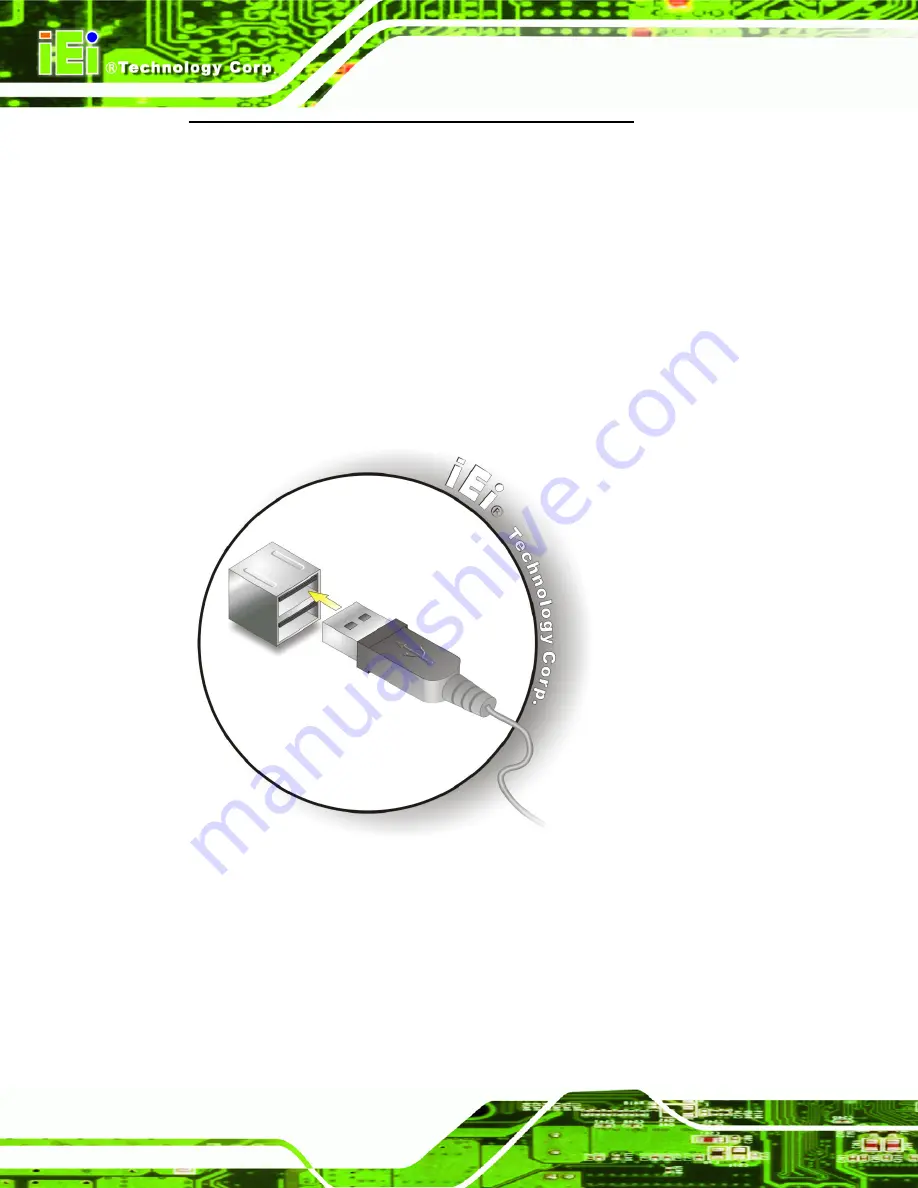
Align the connectors.
Align the USB device connector with one of the
connectors on the bottom panel. See
Figure 2-22
.
Figure 2-22: USB Device Connection
Step 3:
Insert the device connector.
Once aligned, gently insert the USB device
connector into the onboard connector.
Step 0:
2.8 Power Connection
The power cable connects the power adapter to the power outlet. The power adapter and
power cable are required for operation of the panel PC.
Summary of Contents for AFL-08B-N270
Page 13: ...AFL 08B N270 User Manual Page 13 Chapter 1 1 Introduction ...
Page 22: ...AFL 08B N270 User Manual Page 22 Chapter 2 2 Installation ...
Page 52: ...AFL 08B N270 User Manual Page 52 Chapter 3 3 System Maintenance ...
Page 59: ...AFL 08B N270 User Manual Page 59 Chapter 4 4 BIOS Options ...
Page 92: ...AFL 08B N270 User Manual Page 92 5 Interface Connectors Chapter 5 ...
Page 110: ...AFL 08B N270 User Manual Page 110 Appendix A A Safety Precautions ...
Page 115: ...AFL 08B N270 User Manual Page 115 Appendix B B BIOS Options ...
Page 118: ...AFL 08B N270 User Manual Page 118 Appendix C C ALC892 Digital Microphone Configuration ...
Page 122: ...AFL 08B N270 User Manual Page 122 Appendix D D Terminology ...
Page 126: ...AFL 08B N270 User Manual Page 126 Appendix E E Watchdog Timer ...
Page 129: ...AFL 08B N270 User Manual Page 129 Appendix F F Hazardous Materials Disclosure ...


