AFL-08B-N270 User Manual
Page 99
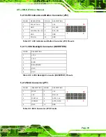
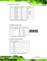
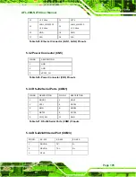
5.2.10 LED Indicator and Button Connector (JP2)
PIN NO.
DESCRIPTION
PIN NO.
DESCRIPTION
1 PW_LED
+5V
2 +5V
3 GND
4 HD_LED
5
SUS PW LED +5V 6 RST_SW
7 GND
8 GND
9 PW_BN
10 GND
2
10
y
y
y
y
y
y
y
y
y
y
1
9
Table 5-11: LED Indicator and Button Connector (JP2) Pinouts
5.2.11 LVDS Backlight Connector (INVERTER1)
5.2.12 MCU Connector (JP7)
PIN NO.
DESCRIPTION PIN NO.
DESCRIPTION
1 MCLR 2 +5V
3 +5V 4 MCU_IR
5 ICSPCLK
6 AUTO_CLK
7 ICSPDAT
8 AUTO_DATA
9 GND 10
GND
2
10
y
y
y
y
y
y
y
y
y
y
1
9
Table 5-13: MCU Connector (JP7) Pinouts
PIN NO.
DESCRIPTION
1 +12V
2 +12V
3 BLON
4 BRIGHTNESS
5 GND
6 GND
Table 5-12: LVDS Backlight Connector (INVERTER1) Pinouts
Summary of Contents for AFL-08B-N270
Page 13: ...AFL 08B N270 User Manual Page 13 Chapter 1 1 Introduction ...
Page 22: ...AFL 08B N270 User Manual Page 22 Chapter 2 2 Installation ...
Page 52: ...AFL 08B N270 User Manual Page 52 Chapter 3 3 System Maintenance ...
Page 59: ...AFL 08B N270 User Manual Page 59 Chapter 4 4 BIOS Options ...
Page 92: ...AFL 08B N270 User Manual Page 92 5 Interface Connectors Chapter 5 ...
Page 110: ...AFL 08B N270 User Manual Page 110 Appendix A A Safety Precautions ...
Page 115: ...AFL 08B N270 User Manual Page 115 Appendix B B BIOS Options ...
Page 118: ...AFL 08B N270 User Manual Page 118 Appendix C C ALC892 Digital Microphone Configuration ...
Page 122: ...AFL 08B N270 User Manual Page 122 Appendix D D Terminology ...
Page 126: ...AFL 08B N270 User Manual Page 126 Appendix E E Watchdog Timer ...
Page 129: ...AFL 08B N270 User Manual Page 129 Appendix F F Hazardous Materials Disclosure ...


