AFL-517A-GM45 User Manual
Page 58
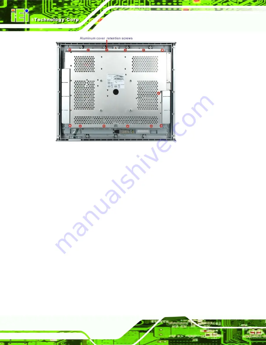
Figure 3-2: Aluminum Cover Retention Screws
Step 6:
Remove the aluminum cover.
3.4 Memory Module Replacement
The flat panel PC is preinstalled with a 2 GB DDR2 memory module. If the memory
module fails, follow the instructions below to replace the memory module.
Step 1:
Remove the back cover and inner aluminum back cover. See
Section 3.3
above.
Step 2:
Locate the SATA cable. Remove the retention screws. Disconnect the cable
from the SATA connector on the ODD.
Step 3:
Locate the SATA ODD bay bracket. Remove the retention screws.
Step 4:
Remove the bracket.
Summary of Contents for AFL-517A-GM45
Page 12: ...AFL 517A GM45 User Manual Page 12 Chapter 1 1 Introduction...
Page 21: ...AFL 517A GM45 User Manual Page 21 Chapter 2 2 Installation...
Page 55: ...AFL 517A GM45 User Manual Page 55 Chapter 3 3 System Maintenance...
Page 65: ...AFL 517A GM45 User Manual Page 65 Chapter 4 4 BIOS Options...
Page 103: ...AFL 517A GM45 User Manual Page 103 Chapter 5 5 iSMM...
Page 119: ...AFL 517A GM45 User Manual Page 119 Appendix A A Safety Precautions...
Page 123: ...AFL 517A GM45 User Manual Page 123 Appendix B B BIOS Options...
Page 126: ...AFL 517A GM45 User Manual Page 126 Appendix C C Terminology...
Page 130: ...AFL 517A GM45 User Manual Page 130 Appendix D D Watchdog Timer...
Page 133: ...AFL 517A GM45 User Manual Page 133 Appendix E E Hazardous Materials Disclosure...


