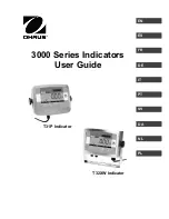
AFL2-17AB-H61
Page X
Lis t o f Fig u re s
Figure 1-1: AFL2-17AB-H61 Flat Bezel Panel PC
........................................................................ 2
Figure 1-2: AFL2-17AB-H61 Front View
........................................................................................ 5
Figure 1-5: AFL2-17AB-H61 Rear View
......................................................................................... 8
Figure 1-6: AFL2-17AB-H61 Bottom Panel
................................................................................... 9
Figure 1-7: AFL2-17AB-H61 Left Side Panel
..............................................................................10
Figure 1-8: AFL2-17AB-H61 Right Side Panel
...........................................................................10
Figure 2-1: AFL2-17AB-H61 Dimensions (mm)
..........................................................................14
Figure 2-3: RJ-45 Ethernet Connector (Bottom Panel)
.............................................................16
Figure 2-4: RJ-45 Ethernet Connector (Left Side Panel)
..........................................................17
Figure 2-5: External USB Ports (Bottom Panel)
........................................................................17
Figure 2-6: External USB Ports (Left Side Panel)
......................................................................18
Figure 4-1: HDD Cover Retention Screws
..................................................................................27
Figure 4-3: Removing the HDD Bracket
.....................................................................................28
Figure 4-6: Insert the K-type Temperature Sensor Cable
.........................................................30
Figure 4-7: Connect the RFID USB cable
...................................................................................30
Figure 4-8: Install the RFID module
............................................................................................31
Figure 4-10: Install the DVD-ROM
...............................................................................................32
Figure 4-11: DVD-ROM Bracket Screws
.....................................................................................33
Figure 4-13: AT/ATX Switch Location
.........................................................................................34
Figure 4-14: Clear CMOS Switch Location
.................................................................................35
Figure 4-15: Reset Button Location
............................................................................................35
Figure 4-16: Wall-mounting Bracket
...........................................................................................37
Summary of Contents for AFL2-17AB-H61 Series
Page 15: ......
Page 17: ...AFL2 17AB H61 Page 1 1 Introduction Chapter 1...
Page 29: ...AFL2 17AB H61 Page 13 2 Detailed Specifications Chapter 2...
Page 35: ...AFL2 17AB H61 Page 19 3 Unpacking Chapter 3...
Page 40: ...AFL2 17AB H61 Page 24 4 Ins tallation Chapter 4...
Page 70: ...AFL2 17AB H61 Page 54 Chapter 5 5 Sys tem Motherboard...
Page 106: ...AFL2 17AB H61 Page 90 Figure 5 36 LCD panel Selection Jumper Location...
Page 107: ...AFL2 17AB H61 Page 91 6 Sys tem Maintenance Chapter 6...
Page 116: ...AFL2 17AB H61 Page 100 7 BIOS Setup Chapter 7...
Page 153: ...AFL2 17AB H61 Panel PC Page 137 8 Cooling Management Cons ole iCMC Chapter 7...
Page 162: ...AFL2 17AB H61 Panel PC Page 146 Appendix A A Regulatory Compliance...
Page 167: ...AFL2 17AB H61 Panel PC Page 151 B Safety Precautions Appendix B...
Page 173: ...AFL2 17AB H61 Panel PC Page 157 C BIOS Menu Options Appendix C...
Page 176: ...AFL2 17AB H61 Panel PC Page 160 D Hazardous Materials Dis clos ure Appendix D...


