AFL2-17AB-H61
P a g e 99
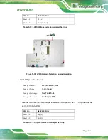
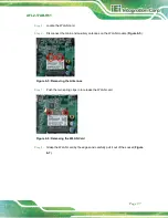
S te p 12:
Replace the internal aluminum cover and secure it to the chassis using seven (7)
retention screws.
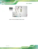
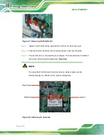
S te p 13:
Replace the back cover and secure it using fourteen (14) previously removed
retention screws.
S te p 0:
6.6
Re in s ta llin g th e Co ve rs
WARNING:
Failing to reinstall the covers may result in permanent damage to the
system. Please make sure all coverings are properly installed.
When maintenance procedures are complete, please make sure all the covers are
replaced, including the following:
Aluminum internal cover
Plastic back cover
Summary of Contents for AFL2-17AB-H61 Series
Page 15: ......
Page 17: ...AFL2 17AB H61 Page 1 1 Introduction Chapter 1...
Page 29: ...AFL2 17AB H61 Page 13 2 Detailed Specifications Chapter 2...
Page 35: ...AFL2 17AB H61 Page 19 3 Unpacking Chapter 3...
Page 40: ...AFL2 17AB H61 Page 24 4 Ins tallation Chapter 4...
Page 70: ...AFL2 17AB H61 Page 54 Chapter 5 5 Sys tem Motherboard...
Page 106: ...AFL2 17AB H61 Page 90 Figure 5 36 LCD panel Selection Jumper Location...
Page 107: ...AFL2 17AB H61 Page 91 6 Sys tem Maintenance Chapter 6...
Page 116: ...AFL2 17AB H61 Page 100 7 BIOS Setup Chapter 7...
Page 153: ...AFL2 17AB H61 Panel PC Page 137 8 Cooling Management Cons ole iCMC Chapter 7...
Page 162: ...AFL2 17AB H61 Panel PC Page 146 Appendix A A Regulatory Compliance...
Page 167: ...AFL2 17AB H61 Panel PC Page 151 B Safety Precautions Appendix B...
Page 173: ...AFL2 17AB H61 Panel PC Page 157 C BIOS Menu Options Appendix C...
Page 176: ...AFL2 17AB H61 Panel PC Page 160 D Hazardous Materials Dis clos ure Appendix D...


