AFL2-17AB-H61
P a g e 8
Ke y Co m b in a tio n
Fu n c tio n Ke y De s c rip tio n
Fn + Brightness Up
Power On/Off
Note: To power on the system, hold down the Fn +
Brightness Up buttons for 3 seconds. To power down the
system, hold down the FN + Brightness Up buttons for six
seconds.
Fn: The function key can maintain for 2sec.
Table 1-3: Function Key Descriptions
1.3
Re a r P a n e l
The rear panel provides access to retention screw holes that support various mounting.
Refer to
Figure 1-5: AFL2-17AB-H61 Rear View
1.4
Bo tto m P a n e l
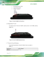
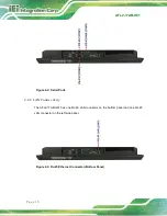
The bottom panel of the AFL2-17AB-H61 has the following features (
):
1 x AT/ATX Switch
1 x Clear CMOS switch
Summary of Contents for AFL2-17AB-H61 Series
Page 15: ......
Page 17: ...AFL2 17AB H61 Page 1 1 Introduction Chapter 1...
Page 29: ...AFL2 17AB H61 Page 13 2 Detailed Specifications Chapter 2...
Page 35: ...AFL2 17AB H61 Page 19 3 Unpacking Chapter 3...
Page 40: ...AFL2 17AB H61 Page 24 4 Ins tallation Chapter 4...
Page 70: ...AFL2 17AB H61 Page 54 Chapter 5 5 Sys tem Motherboard...
Page 106: ...AFL2 17AB H61 Page 90 Figure 5 36 LCD panel Selection Jumper Location...
Page 107: ...AFL2 17AB H61 Page 91 6 Sys tem Maintenance Chapter 6...
Page 116: ...AFL2 17AB H61 Page 100 7 BIOS Setup Chapter 7...
Page 153: ...AFL2 17AB H61 Panel PC Page 137 8 Cooling Management Cons ole iCMC Chapter 7...
Page 162: ...AFL2 17AB H61 Panel PC Page 146 Appendix A A Regulatory Compliance...
Page 167: ...AFL2 17AB H61 Panel PC Page 151 B Safety Precautions Appendix B...
Page 173: ...AFL2 17AB H61 Panel PC Page 157 C BIOS Menu Options Appendix C...
Page 176: ...AFL2 17AB H61 Panel PC Page 160 D Hazardous Materials Dis clos ure Appendix D...


