AFL2-17AB-H61
P a g e 38
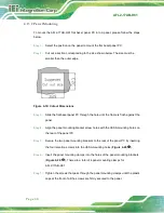
S te p 6:
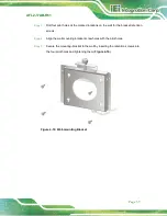
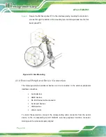
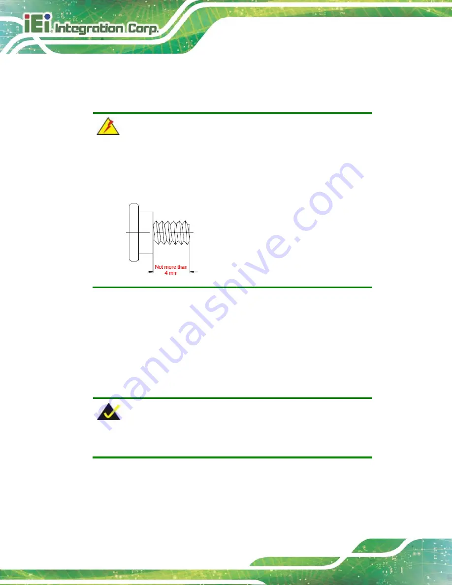
Insert the four monitor mounting screws provided in the wall mount kit into the
four screw holes on the real panel of the flat bezel panel PC and tighten until the
screw shank is secured against the rear panel (
WARNING:
Please use the M4 screws provided in the wall mount kit for the rear panel.
If the screw is missing, the thread depth of the replacement screw should
be not more than 4 mm.
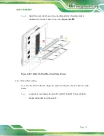
S te p 7:
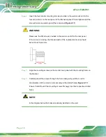
Align the mounting screws on the monitor rear panel with the mounting holes on
the bracket.
S te p 8:
Carefully insert the screws through the holes and gently pull the monitor
downwards until the monitor rests securely in the slotted holes (
Ensure that all four of the mounting screws fit snugly into their respective slotted
holes.
NOTE:
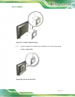
In the diagram below the bracket is already installed on the wall.
Summary of Contents for AFL2-17AB-H61 Series
Page 15: ......
Page 17: ...AFL2 17AB H61 Page 1 1 Introduction Chapter 1...
Page 29: ...AFL2 17AB H61 Page 13 2 Detailed Specifications Chapter 2...
Page 35: ...AFL2 17AB H61 Page 19 3 Unpacking Chapter 3...
Page 40: ...AFL2 17AB H61 Page 24 4 Ins tallation Chapter 4...
Page 70: ...AFL2 17AB H61 Page 54 Chapter 5 5 Sys tem Motherboard...
Page 106: ...AFL2 17AB H61 Page 90 Figure 5 36 LCD panel Selection Jumper Location...
Page 107: ...AFL2 17AB H61 Page 91 6 Sys tem Maintenance Chapter 6...
Page 116: ...AFL2 17AB H61 Page 100 7 BIOS Setup Chapter 7...
Page 153: ...AFL2 17AB H61 Panel PC Page 137 8 Cooling Management Cons ole iCMC Chapter 7...
Page 162: ...AFL2 17AB H61 Panel PC Page 146 Appendix A A Regulatory Compliance...
Page 167: ...AFL2 17AB H61 Panel PC Page 151 B Safety Precautions Appendix B...
Page 173: ...AFL2 17AB H61 Panel PC Page 157 C BIOS Menu Options Appendix C...
Page 176: ...AFL2 17AB H61 Panel PC Page 160 D Hazardous Materials Dis clos ure Appendix D...

