AFL2-17AB-H61
P a g e 44
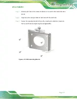
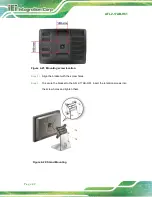
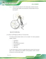
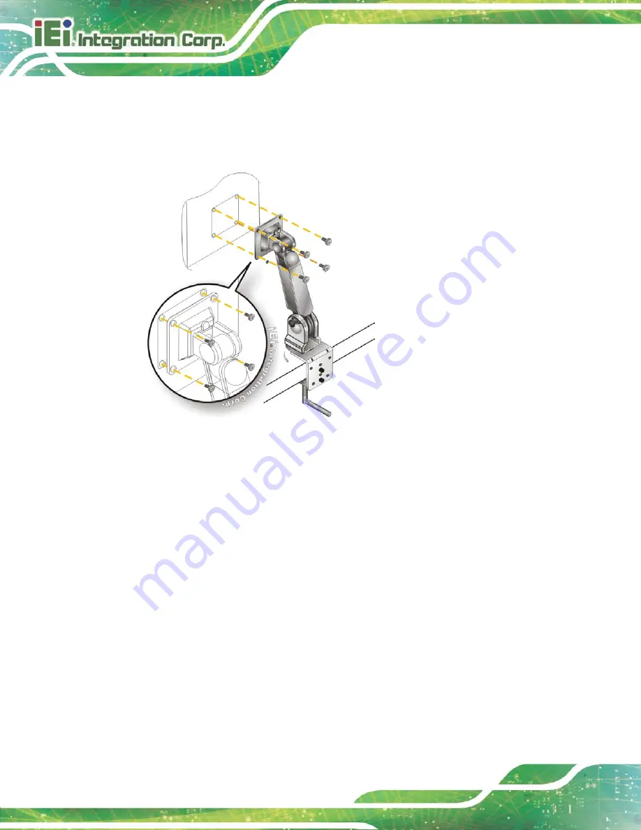
S te p 4:
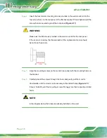
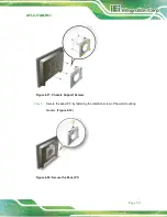
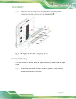
Secure the flat bezel panel PC to the interface pad by inserting four retention
screws through the bottom of the mounting arm interface pad and into the flat
bezel panel PC.
Figure 4-24: Arm Mounting
4.14
Exte rn a l P e rip h e ra l De vic e Co n n e c tio n
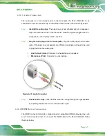
The following external peripheral devices can be connected to the external peripheral
interface connectors.
Audio devices
HDMI devices
RJ-45 Ethernet cable connector
Serial port devices
USB devices
VGA monitor
To install these devices, connect the corresponding cable connector from the actual
device to the corresponding AFL2-17AB-H61 external peripheral interface connector
making sure the pins are properly aligned.
Summary of Contents for AFL2-17AB-H61 Series
Page 15: ......
Page 17: ...AFL2 17AB H61 Page 1 1 Introduction Chapter 1...
Page 29: ...AFL2 17AB H61 Page 13 2 Detailed Specifications Chapter 2...
Page 35: ...AFL2 17AB H61 Page 19 3 Unpacking Chapter 3...
Page 40: ...AFL2 17AB H61 Page 24 4 Ins tallation Chapter 4...
Page 70: ...AFL2 17AB H61 Page 54 Chapter 5 5 Sys tem Motherboard...
Page 106: ...AFL2 17AB H61 Page 90 Figure 5 36 LCD panel Selection Jumper Location...
Page 107: ...AFL2 17AB H61 Page 91 6 Sys tem Maintenance Chapter 6...
Page 116: ...AFL2 17AB H61 Page 100 7 BIOS Setup Chapter 7...
Page 153: ...AFL2 17AB H61 Panel PC Page 137 8 Cooling Management Cons ole iCMC Chapter 7...
Page 162: ...AFL2 17AB H61 Panel PC Page 146 Appendix A A Regulatory Compliance...
Page 167: ...AFL2 17AB H61 Panel PC Page 151 B Safety Precautions Appendix B...
Page 173: ...AFL2 17AB H61 Panel PC Page 157 C BIOS Menu Options Appendix C...
Page 176: ...AFL2 17AB H61 Panel PC Page 160 D Hazardous Materials Dis clos ure Appendix D...

