AFL2-W07A-N26
P a g e 53
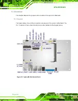
5.3
Exte rn a l In te rfa c e P a n e l Co n n e c to rs
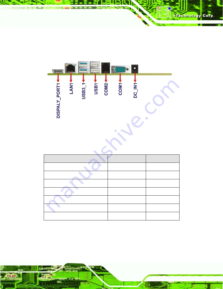
The figures below show all the external interface panel connectors on the system
motherboard.
Figure 5-3: External Interface Panel Connectors
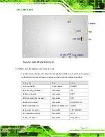
The table below shows a list of the external interface panel connectors on the system
motherboard. Pinouts of these connectors can be found in the following sections.
Co n n e c to r
Typ e
La b e l
Display port connector
Display port
DISPLAY_PORT1
Ethernet connector
RJ-45
LAN1
Power connector
Power jack
DC_IN1
RS-232 serial port connector
DB-9
COM1
RS-232 serial port connector
RJ11
COM2
USB 2.0 connectors
USB 2.0 port
USB1
USB 3.0 connectors
USB 3.0 port
USB3_1
Table 5-25: Rear Panel Connectors
Summary of Contents for AFL2-W07A-N26
Page 2: ...AFL2 W07A N26 Page II Revis ion Date Version Changes 19 February 2013 1 00 Initial release...
Page 17: ...AFL2 W07A N26 Page 1 1 Introduction Chapter 1...
Page 27: ...AFL2 W07A N26 Page 11 2 Detailed Specifications Chapter 2...
Page 33: ...AFL2 W07A N26 Page 17 3 Unpacking Chapter 3...
Page 37: ...AFL2 W07A N26 Page 21 4 Ins tallation Chapter 4...
Page 59: ...AFL2 W07A N26 Page 43 5 Sys tem Motherboard Chapter 5...
Page 73: ...AFL2 W07A N26 Page 57 6 Sys tem Maintenance Chapter 6...
Page 83: ...AFL2 W07A N26 Page 67 7 BIOS Setup Chapter 7...
Page 111: ...AFL2 W07A N26 Page 95 8 Software Drivers Chapter 8...
Page 143: ...AFL2 W07A N26 Page 127 A Safety Precautions Appendix A...
Page 148: ...AFL2 W07A N26 Page 132 B BIOS Menu Options Appendix B...
Page 151: ...AFL2 W07A N26 Page 135 Appendix C C One Key Recovery...
Page 159: ...AFL2 W07A N26 Page 143 Figure C 5 Partition Creation Commands...
Page 192: ...AFL2 W07A N26 Page 176 D Hazardous Materials Dis clos ure Appendix D...


