AFL2-W15A-N270/L325 Panel PC
Page 47
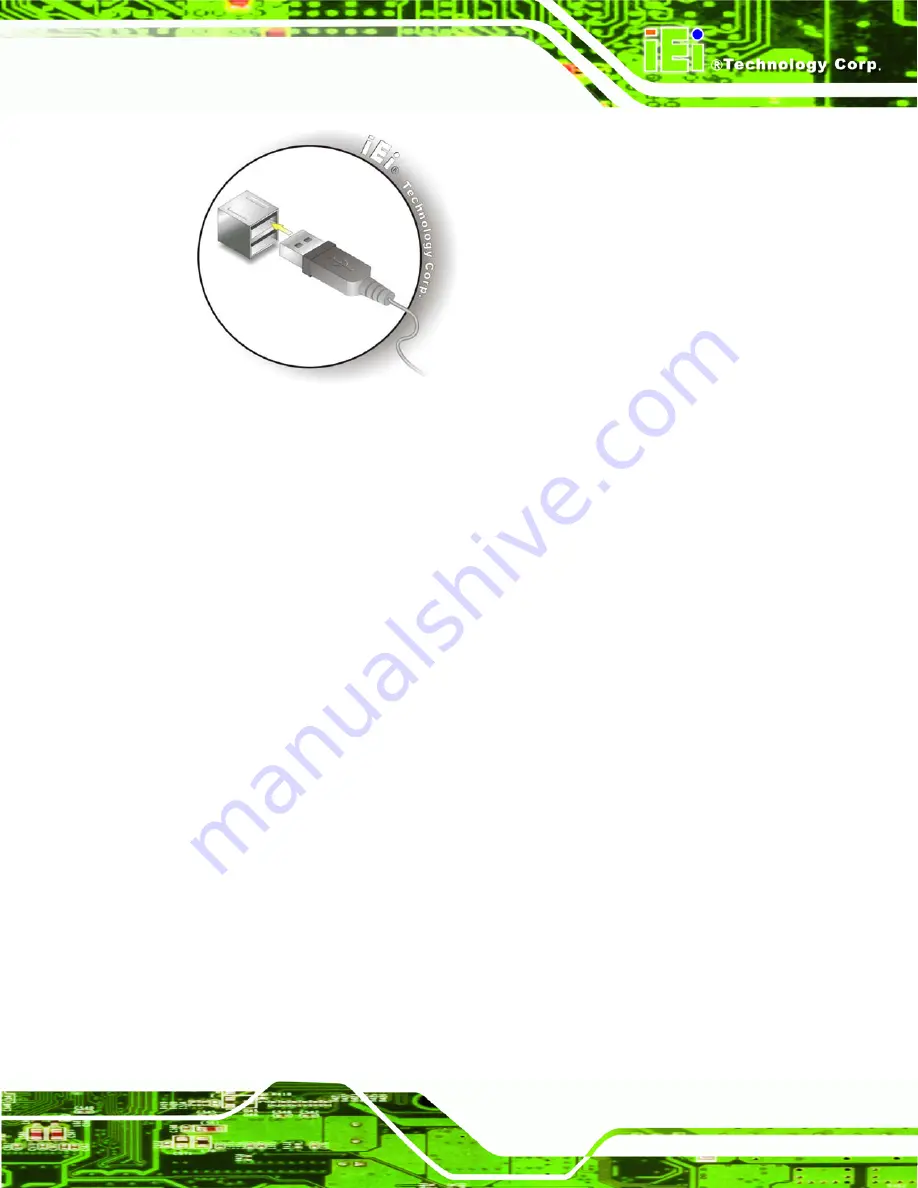
Figure 2-29: USB Device Connection
Step 3:
Insert the device connector.
Once aligned, gently insert the USB device
connector into the onboard connector.
Step 0:
2.9.4 VGA Monitor Connection
The VGA output can be connected to an external VGA monitor. To connect the VGA
monitor to the AFL2-W15A-N270/L325, please follow the instructions below.
Step 1:
Locate the female DB-15 connector
. The location of the female DB-15
connector is shown in
Chapter 3
.
Step 2:
Align the VGA connector
. Align the male DB-15 connector on the VGA screen
cable with the female DB-15 connector on the external peripheral interface.
Step 3:
Insert the VGA connector
.
Once the connectors are properly aligned with the
insert the male connector from the VGA screen into the female connector on the
AFL2-W15A-N270/L325. See Figure 2-30.
Summary of Contents for AFL2-W15A-N270/L325
Page 13: ...AFL2 W15A N270 L325 Panel PC Page 1 Chapter 1 1 Introduction...
Page 22: ...AFL2 W15A N270 L325 Panel PC Page 10 Chapter 2 2 Installation...
Page 64: ...AFL2 W15A N270 L325 Panel PC Page 52 Chapter 3 3 BIOS Setup...
Page 109: ...AFL2 W15A N270 L325 Panel PC Page 97 Chapter 4 4 System Maintenance...
Page 113: ...AFL2 W15A N270 L325 Panel PC Page 101 Appendix A A Safety Precautions...
Page 118: ...AFL2 W15A N270 L325 Panel PC Page 106 Appendix B B One Key Recovery...
Page 146: ...AFL2 W15A N270 L325 Panel PC Page 134 Appendix C C BIOS Options...
Page 150: ...AFL2 W15A N270 L325 Panel PC Page 138 Appendix D D Expansion Module Dimensions...
Page 153: ...AFL2 W15A N270 L325 Panel PC Page 141 Appendix E E Terminology...
Page 157: ...AFL2 W15A N270 L325 Panel PC Page 145 Appendix F F Watchdog Timer...
Page 160: ...AFL2 W15A N270 L325 Panel PC Page 148 Appendix G G Hazardous Materials Disclosure...
Page 164: ...AFL2 W15A N270 L325 Panel PC Page 152 Appendix H H International Standards Compliance...


