AFL3-W10A/12A/W15A-BT Panel PC
Page 23
Step 2:
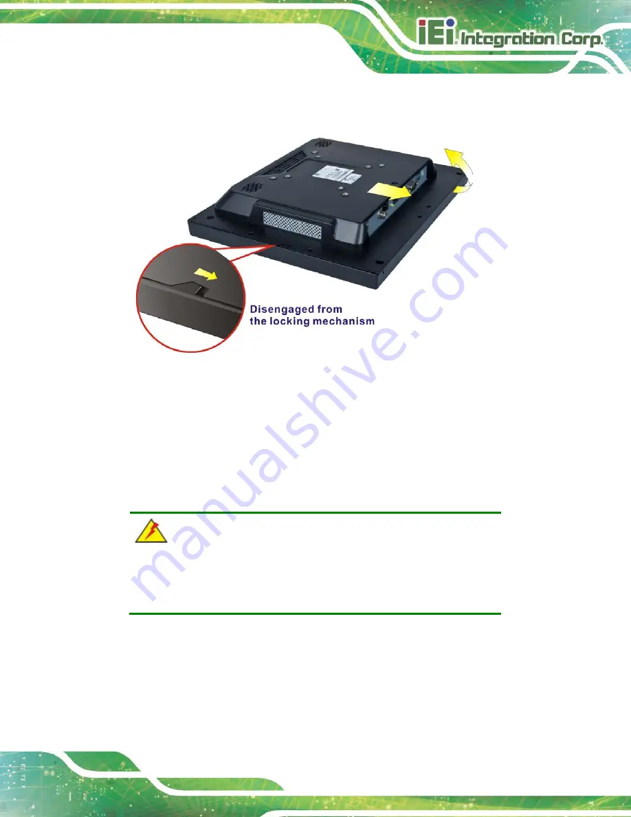
Slide the back cover toward the I/O panel until it is disengaged from the locking
mechanism. Then, lift the back cover off the chassis. See
Figure 3-4: Remove the Back Cover
3.4.1 Reinstalling the Back Cover
To install the back cover, slide the back cover toward the top cover until the external and
internal locking mechanisms are both clipped into place. Then, secure the back cover with
the previously removed screws. Please be aware of the type of screws when fastening the
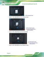
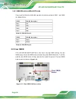
back cover of the 12.1" and 15" models (refer to Figure 3-2 and Figure 3-3).
WARNING:
Over-tightening back cover screws will crack the plastic frame.
Maximum torque for cover screws is 5 kg-cm (0.36 lb-ft/0.49 Nm).
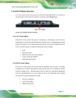
The following diagram shows the differences of the internal locking mechanism of the two
models.
Summary of Contents for AFL3-12A-BT
Page 15: ...AFL3 W10A 12A W15A BT Panel PC Page 1 1 Introduction Chapter 1...
Page 28: ...AFL3 W10A 12A W15A BT Panel PC Page 14 2 Unpacking Chapter 2...
Page 33: ...AFL3 W10A 12A W15A BT Panel PC Page 19 3 Installation Chapter 3...
Page 69: ...AFL3 W10A 12A W15A BT Panel PC Page 55 4 BIOS Setup Chapter 4...
Page 101: ...AFL3 W10A 12A W15A BT Panel PC Page 87 5 System Maintenance Chapter 5...
Page 106: ...AFL3 W10A 12A W15A BT Panel PC Page 92 6 Interface Connectors Chapter 6...
Page 121: ...AFL3 W10A 12A W15A BT Panel PC Page 107 Appendix A A Regulatory Compliance...
Page 126: ...AFL3 W10A 12A W15A BT Panel PC Page 112 B Safety Precautions Appendix B...
Page 132: ...AFL3 W10A 12A W15A BT Panel PC Page 118 C BIOS Menu Options Appendix C...
Page 135: ...AFL3 W10A 12A W15A BT Panel PC Page 121 Appendix D D Watchdog Timer...
Page 138: ...AFL3 W10A 12A W15A BT Panel PC Page 124 Appendix E E Error Beep Code...
Page 140: ...AFL3 W10A 12A W15A BT Panel PC Page 126 Appendix F F Hazardous Materials Disclosure...


