AFL3-12C-ULT3 Panel PC
Page 17
Anti-static Discharge
: If a user open the rear panel of the flat bezel panel PC,
to configure the jumpers or plug in added peripheral devices, ground
themselves first and wear an anti-static wristband.
3.3 Installation and Configuration Steps
The following installation steps must be followed.
Step 1:
Unpack the flat bezel panel PC.
Step 2:
Install an mSATA module or an HDD.
Step 3:
Connect peripheral devices to the flat bezel panel PC.
Step 4:
Mount the flat bezel panel PC.
Step 0:
3.4 Removing the Back Covers
To access the AFL3-12C-ULT3 internally the plastic back cover and the internal aluminum
cover must be removed. To remove the covers, please follow the steps below.
Step 1:
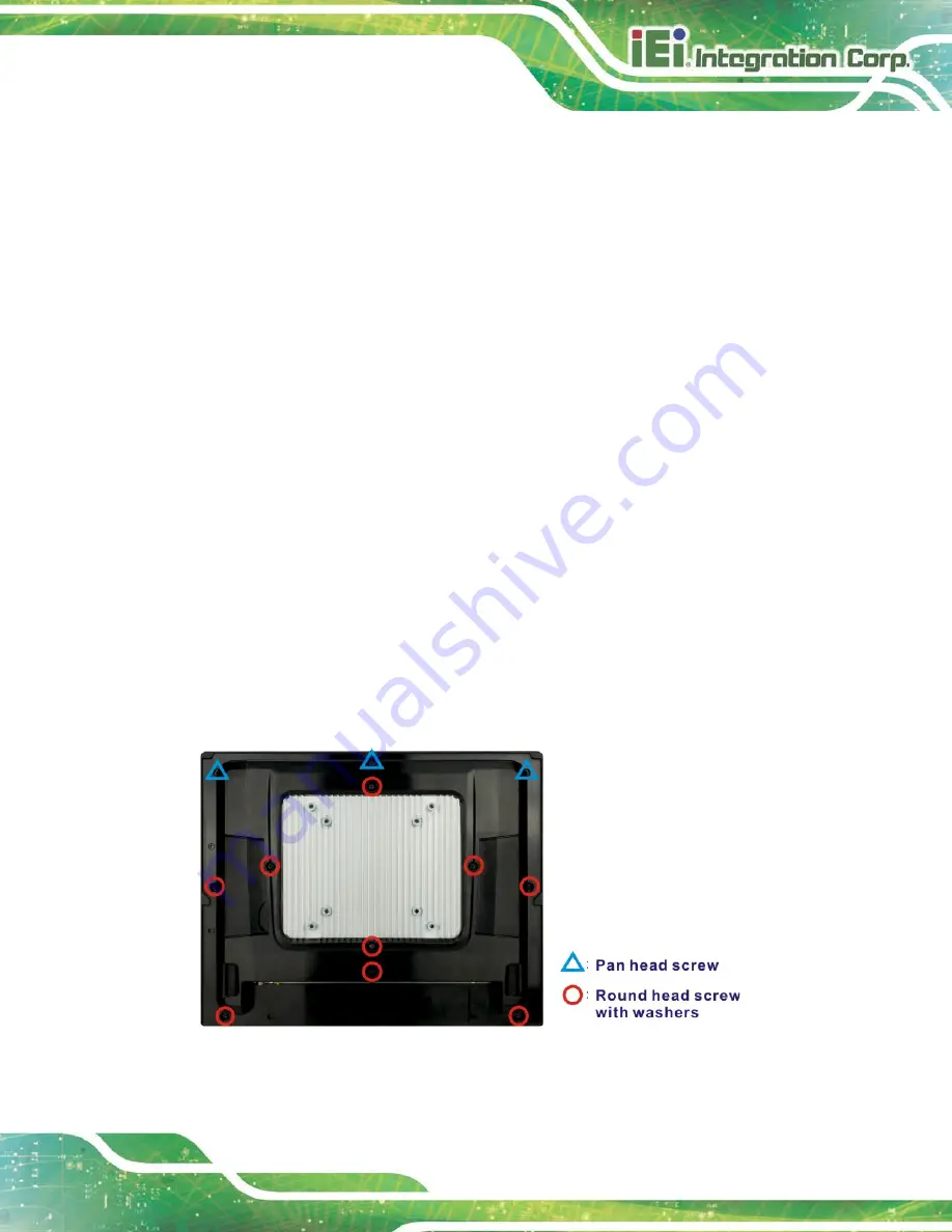
Remove 12 retention screws from the back cover. Two types of screw are used
for securing the plastic cover of the AFL3-12C-ULT3. Be aware of this for
reinstalling the plastic cover. See
Figure 3-1: Back Cover Retention Screws
Summary of Contents for AFL3-12C-ULT3
Page 2: ...AFL3 12C ULT3 Panel PC Page II Revision Date Version Changes May 7 2018 1 00 Initial release...
Page 16: ......
Page 17: ...AFL3 12C ULT3 Panel PC Page 1 1 Introduction Chapter 1...
Page 26: ...AFL3 12C ULT3 Panel PC Page 10 2 Unpacking Chapter 2...
Page 31: ...AFL3 12C ULT3 Panel PC Page 15 3 Installation Chapter 3...
Page 61: ...AFL3 12C ULT3 Panel PC Page 45 4 BIOS Setup Chapter 4...
Page 95: ...AFL3 12C ULT3 Panel PC Page 79 5 System Maintenance Chapter 5...
Page 100: ...AFL3 12C ULT3 Panel PC Page 84 6 Interface Connectors Chapter 6...
Page 119: ...AFL3 12C ULT3 Panel PC Page 103 Appendix A A Regulatory Compliance...
Page 125: ...AFL3 12C ULT3 Panel PC Page 109 B Safety Precautions Appendix B...
Page 131: ...AFL3 12C ULT3 Panel PC Page 115 C BIOS Menu Options Appendix C...
Page 134: ...AFL3 12C ULT3 Panel PC Page 118 Appendix D D Watchdog Timer...
Page 137: ...AFL3 12C ULT3 Panel PC Page 121 Appendix E E Hazardous Materials Disclosure...


