AFL3-12C-ULT3 Panel PC
Page 21
Step 6:
Re-install the aluminum cover and the plastic back cover.
Step 0:
NOTE:
To install a half-size mSATA module, remove both the retention screw
and standoff of the PCIe Mini card slot, and install the standoff into the
screw hole for the half-size card. Insert the half-size mSATA module
into the socket. Then, secure the module with the previously removed
retention screw.
3.6 HDD Installation
To install the HDD into the system, please follow the steps below:
Step 1:
Remove the plastic back cover and the internal aluminum cover. See
Section 3.4
above.
Step 2:
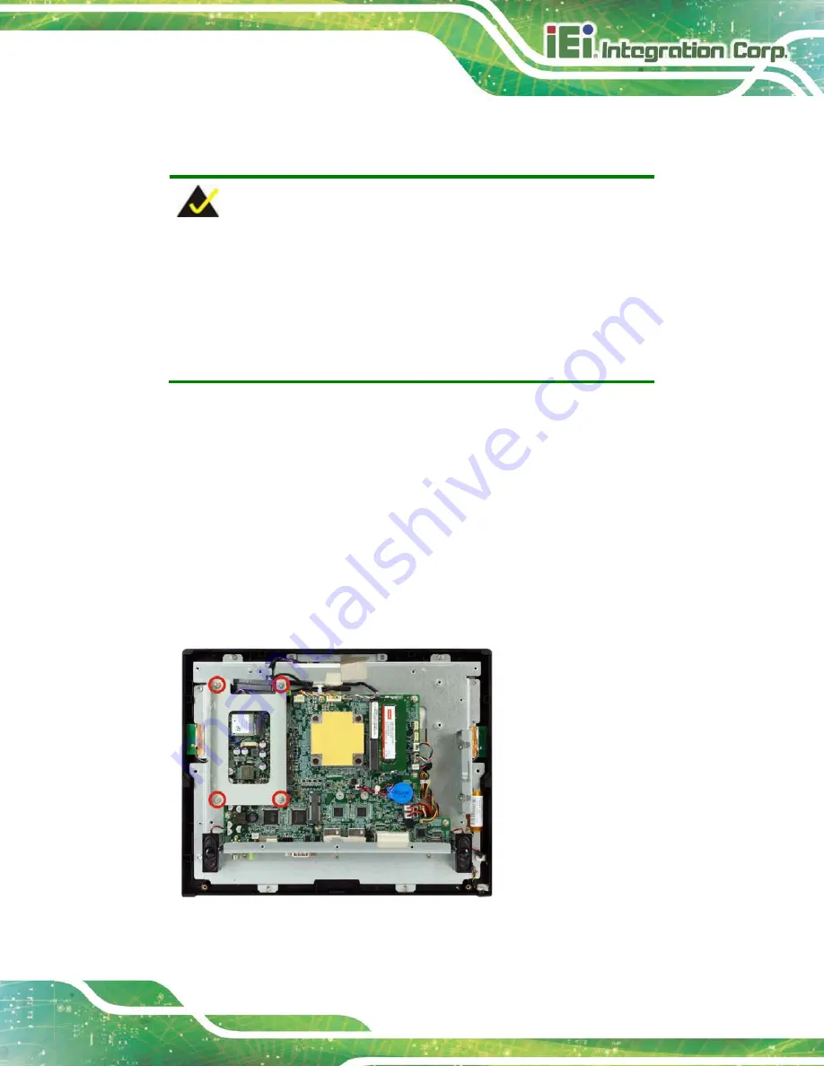
Remove the four HDD bracket retention screws and lift the HDD bracket off the
panel PC.
Figure 3-7: HDD Bracket Retention Screws
Summary of Contents for AFL3-12C-ULT3
Page 2: ...AFL3 12C ULT3 Panel PC Page II Revision Date Version Changes May 7 2018 1 00 Initial release...
Page 16: ......
Page 17: ...AFL3 12C ULT3 Panel PC Page 1 1 Introduction Chapter 1...
Page 26: ...AFL3 12C ULT3 Panel PC Page 10 2 Unpacking Chapter 2...
Page 31: ...AFL3 12C ULT3 Panel PC Page 15 3 Installation Chapter 3...
Page 61: ...AFL3 12C ULT3 Panel PC Page 45 4 BIOS Setup Chapter 4...
Page 95: ...AFL3 12C ULT3 Panel PC Page 79 5 System Maintenance Chapter 5...
Page 100: ...AFL3 12C ULT3 Panel PC Page 84 6 Interface Connectors Chapter 6...
Page 119: ...AFL3 12C ULT3 Panel PC Page 103 Appendix A A Regulatory Compliance...
Page 125: ...AFL3 12C ULT3 Panel PC Page 109 B Safety Precautions Appendix B...
Page 131: ...AFL3 12C ULT3 Panel PC Page 115 C BIOS Menu Options Appendix C...
Page 134: ...AFL3 12C ULT3 Panel PC Page 118 Appendix D D Watchdog Timer...
Page 137: ...AFL3 12C ULT3 Panel PC Page 121 Appendix E E Hazardous Materials Disclosure...


