background image


AFL3-12C-ULT3 Panel PC 


Page 22 

Step 3: 

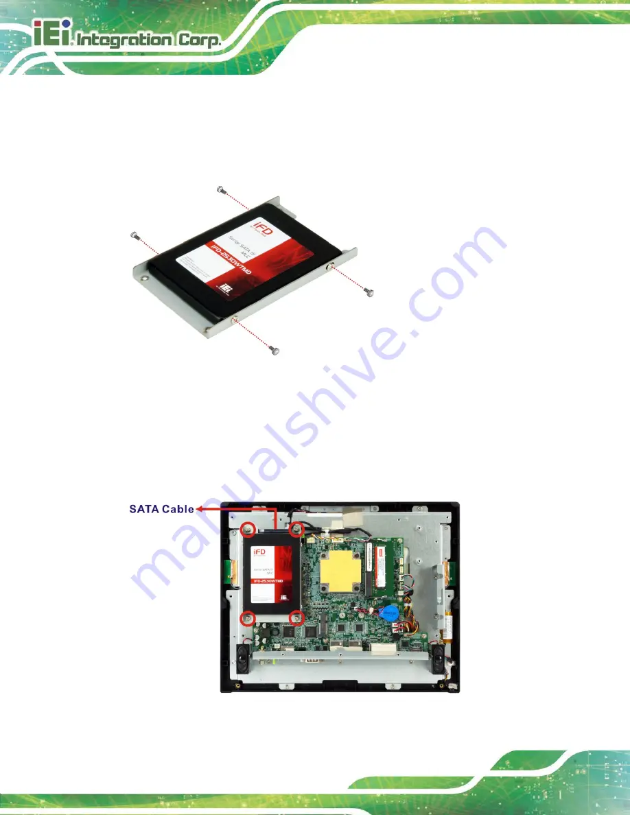
Attach the HDD brackets to the HDD. To do this, align the four retention screw 

holes in the both sides of the HDD bracket with the retention screw holes on the 

sides of the HDD. Insert four retention screws (M3*4) into the HDD bracket   

(

Figure 3-8

).   


Figure 3-8: HDD Retention Screws 

Step 4: 

Install the HDD into the AFL3-12C-ULT3 by aligning the retention screw holes in 

the HDD brackets with the retention screw holes on the chassis. Insert the four 

retention screws.   

Step 5: 

Connect the SATA cable to the rear of HDD from the motherboard. 


Figure 3-9: HDD Installation 

Summary of Contents for AFL3-12C-ULT3

Page 1: ...age I User Manual AFL3 12C ULT3 MODEL Flat Bezel Panel PC with Intel Core i5 6300U Celeron 3855U CPU Touchscreen Four USB Ports Dual GbE LAN RS 232 422 485 HDMI Wi Fi 802 11a b g n ac and RoHS Rev 1 0...

Page 2: ...AFL3 12C ULT3 Panel PC Page II Revision Date Version Changes May 7 2018 1 00 Initial release...

Page 3: ...eating do not operate it in an area that exceeds the maximum operating temperature described in the user manual Vorsicht Um eine berhitzung des Systems zu vermeiden betreiben Sie es ausschlie lich im...

Page 4: ...di un altro tipo di adattatore pu causare rischio d incendio o esplosione Si prega di fare riferimento al manuale utente per le specifiche sull alimentazione Atenci n Utilice solamente el adaptador d...

Page 5: ...arising out of the use or inability to use the product or documentation even if advised of the possibility of such damages This document contains proprietary information protected by copyright All ri...

Page 6: ...ON Cautionary messages should be heeded to help reduce the chance of losing data or damaging the product NOTE These messages inform the reader of essential but non critical information These messages...

Page 7: ...L ITEMS 13 3 INSTALLATION 15 3 1 ANTI STATIC PRECAUTIONS 16 3 2 INSTALLATION PRECAUTIONS 16 3 3 INSTALLATION AND CONFIGURATION STEPS 17 3 4 REMOVING THE BACK COVERS 17 3 5 MSATAMODULE INSTALLATION 18...

Page 8: ...Using Setup 46 4 1 3 Getting Help 47 4 1 4 BIOS Menu Bar 47 4 2 MAIN 48 4 3 ADVANCED 49 4 3 1 ACPI Settings 50 4 3 2 Super IO Configuration 51 4 3 2 1 Serial Port n Configuration 51 4 3 2 1 1 Serial...

Page 9: ...1 6 INTERFACE CONNECTORS 84 6 1 PERIPHERAL INTERFACE CONNECTORS 85 6 2 INTERNAL PERIPHERAL CONNECTORS 86 6 2 1 Audio Connector AUDIO_OUT1 87 6 2 2 Audio Out Connector AUDIO_OUT_L1 87 6 2 1 Audio Out C...

Page 10: ...RS 232 RJ 45 Serial Port COM1 98 6 3 2 RS 232 422 485 DB 9 Serial Port COM2 99 6 3 3 USB 3 0 Connectors USB3_CON1 99 6 3 4 USB 2 0 Connectors USB2_CON1 100 6 4 PRECONFIGURED JUMPER SETTINGS 100 6 4 1...

Page 11: ...ews 21 Figure 3 8 HDD Retention Screws 22 Figure 3 9 HDD Installation 22 Figure 3 10 Serial Device Connector 24 Figure 3 11 AT ATX Switch Location 25 Figure 3 12 Wall mounting Bracket 27 Figure 3 13 C...

Page 12: ...AFL3 12C ULT3 Panel PC Page XII Figure 3 26 IEI Resource Download Center 41 Figure 5 1 SO DIMM module Location 82 Figure 5 2 SO DIMM Installation 82 Figure 6 1 Main Board Layout Diagram 85...

Page 13: ...e Connector DMIC1 Pinouts 90 Table 6 11 PCIe Mini Connector M_PCIE1 Pinouts 91 Table 6 12 Power Button Connector PWR_BTN1 Pinouts 92 Table 6 13 Power LED Connector PW_LED1 Pinouts 92 Table 6 14 SATA C...

Page 14: ...1 RS 232 422 485 DB 9 Serial Port COM2 Pinouts 99 Table 6 32 USB 3 0 Connectors USB_CON12 Pinouts 99 Table 6 33 USB 2 0 Connectors USB2_CON1 Pinouts 100 Table 6 34 Preconfigured Jumpers 100 Table 6 35...

Page 15: ...nsole Redirection Settings 58 BIOS Menu 11 Console Redirection Settings 59 BIOS Menu 12 CPU Configuration 61 BIOS Menu 13 SATA Configuration 63 BIOS Menu 14 USB Configuration 65 BIOS Menu 15 IEI Featu...

Page 16: ......

Page 17: ...AFL3 12C ULT3 Panel PC Page 1 1 Introduction Chapter 1...

Page 18: ...pplications The Intel Core i5 6300U Celeron 3855U is a System on Chip SoC that ensures optimal memory graphics and peripheral I O support The system comes with 4 0 GB of DDR4 SO DIMM memory ensuring s...

Page 19: ...features are listed below Flat bezel LCD with LED backlight Intel Core i5 6300U or Intel Celeron 3855U processor Preinstalled with 4 GB of DDR4 memory system max 8 GB Projected capacitive type touchs...

Page 20: ...BS plastic frame Figure 1 2 Figure 1 2 Front View There is a power LED indicator located on the front panel The status descriptions of the power LED indicator are listed below Off power cord not attac...

Page 21: ...g connectors and switches Figure 1 3 Bottom Panel 1 6 Rear Panel The rear panel has two speakers and retention screw holes that support VESA mounting The rear panel also has several retention screw ho...

Page 22: ...he technical specifications for the AFL3 12C ULT3 systems are listed in Table 1 2 Specification AFL3 12C ULT3 LCD Size 12 1 4 3 Max Resolution 1024 W x 768 H Brightness cd m2 500 Contrast Ratio 700 1...

Page 23: ...r Two 3 W Camera 2 megapixel with low light function and digital microphone Wireless Bluetooth One M 2 2230 M key module supports 802 11a b g n ac WLAN Bluetooth v4 0 E Window Support Yes optional RFI...

Page 24: ...nsumption 72 W 12 V 6 A Intel Core i5 6300U CPU with 4 GB 2133 MHz DDR4 memory IP Level IP 64 compliant front panel Safety EMC CE FCC ErP 2009 125 EC I O Ports and Switches 1 x RS 232 422 485 serial p...

Page 25: ...AFL3 12C ULT3 Panel PC Page 9 1 9 Dimensions The following sections list the dimensions of the AFL3 12C ULT3 Figure 1 6 Dimensions mm...

Page 26: ...AFL3 12C ULT3 Panel PC Page 10 2 Unpacking Chapter 2...

Page 27: ...the box Only cut deep enough to break the tape Step 2 Open the outside box Step 3 Carefully cut the tape sealing the box Only cut deep enough to break the tape Step 4 Open the inside box Step 5 Lift...

Page 28: ...ULT3 flat bezel panel PC is shipped with the following components Quantity Item Image 1 AFL3 12C ULT3 panel PC 1 96 W power adapter 1 Power cord 1 RJ 45 to DB 9 COM port cable 5 Screws M4 6 for VESA...

Page 29: ...The following are optional components which may be separately purchased Item and Part Number Image VESA 100 wall mount kit P N AFLWK 19B Panel mounting kit P N AFL3PK 08A R10 Rack mounting kit P N AF...

Page 30: ...A12 RS Stand for VESA 75 VESA 100 P N STAND C12 R10 LCD monitor stand with adjustable hinge P N VSTAND A12 Magnetic card reader P N AFL3P W10MSR U R10 Barcode scanner P N AFL3 2D R11 If any of these i...

Page 31: ...AFL3 12C ULT3 Panel PC Page 15 3 Installation Chapter 3...

Page 32: ...prevent ESD from damaging the board Self grounding Before handling the board touch any grounded conducting material During the time the board is handled frequently touch any conducting materials that...

Page 33: ...an mSATA module or an HDD Step 3 Connect peripheral devices to the flat bezel panel PC Step 4 Mount the flat bezel panel PC Step 0 3 4 Removing the Back Covers To access the AFL3 12C ULT3 internally...

Page 34: ...Retention Screws Step 4 Lift the aluminum cover off the AFL3 12C ULT3 A thermal pad is attached under the center of the aluminum cover Thus more strength is required when lifting the aluminum cover 3...

Page 35: ...AFL3 12C ULT3 Panel PC Page 19 Figure 3 3 mSATA Module Slot Location Step 3 Remove the retention screw as shown in Figure 3 4 Figure 3 4 Removing the Retention Screw and Standoff...

Page 36: ...PCIe Mini card into the socket at an angle of about 20 Figure 3 5 Figure 3 5 Installing an mSATA Module Step 5 Secure the mSATA module with the retention screw Push the other end of the mSATA module d...

Page 37: ...hole for the half size card Insert the half size mSATA module into the socket Then secure the module with the previously removed retention screw 3 6 HDD Installation To install the HDD into the system...

Page 38: ...sides of the HDD Insert four retention screws M3 4 into the HDD bracket Figure 3 8 Figure 3 8 HDD Retention Screws Step 4 Install the HDD into the AFL3 12C ULT3 by aligning the retention screw holes i...

Page 39: ...r on the bottom panel The COM1 port connects to a cable with a standard D sub 9 connector at the other end cable included Follow the steps below to connect a serial device to the AFL3 12C ULT3 panel P...

Page 40: ...COM1 are listed in the following table Pin No Description Pin No Description 1 DCD 2 RXD 3 TXD 4 DTR 5 GND 6 DSR 7 RTS 8 CTS 9 RI Table 3 1 RS 232 Serial Port COM1 Pinouts 3 7 2 RS 232 422 485 Serial...

Page 41: ...an AT ATX switch located on the bottom panel Figure 3 11 Figure 3 11 AT ATX Switch Location 3 8 1 AT Power Mode With the AT mode selected the power is controlled by a central power unit rather than a...

Page 42: ...llance Point of Sale POS Advertising terminal 3 9 Mounting the System The methods of mounting the AFL3 12C ULT3 are listed below Wall mounting Panel mounting Rack mounting Arm mounting Stand mounting...

Page 43: ...the four pilot holes and tightening them Figure 3 12 Figure 3 12 Wall mounting Bracket Step 6 Insert the four monitor mounting screws provided in the wall mount kit into the four screw holes on the r...

Page 44: ...7 Align the mounting screws on the monitor rear panel with the mounting holes on the bracket Step 8 Carefully insert the screws through the holes and gently pull the monitor downwards until the monit...

Page 45: ...AFL3 12C ULT3 Panel PC Page 29 Figure 3 13 Chassis Support Screws Step 9 Secure the panel PC by fastening the retention screw of the wall mounting bracket Figure 3 14 Figure 3 14 Secure the Panel PC...

Page 46: ...r edge Figure 3 15 Cutout Dimensions Step 3 Slide the panel PC through the hole until the frame is flush against the panel Step 4 Insert a M5 50 screw into the screw hole on the side of the panel moun...

Page 47: ...Figure 3 16 Panel Mounting Kit Installation Step 6 Align the panel mounting bracket screw holes with the VESA mounting holes on the rear of the panel PC Step 7 Secure the two panel mounting brackets t...

Page 48: ...12C ULT3 Panel PC Page 32 Figure 3 17 Securing Panel Mounting Brackets NOTE The panel mounting kit described in this section is an optional item To purchase it please contact an IEI sales representat...

Page 49: ...installed Step 1 Slide the rear chassis of the AFL3 12C ULT3 panel PC through the rack cabinet bracket until the frame is flush against the front of the bracket Step 2 Insert a M5 50 screw into the s...

Page 50: ...p 4 Align the rack mounting bracket screw holes with the VESA mounting holes on the rear of the panel PC Step 5 Secure the two rack mounting brackets to the rear of the panel PC by inserting the four...

Page 51: ...C ULT3 Panel PC Page 35 Figure 3 19 Securing Rack Mounting Brackets Step 6 Slide the panel PC with the attached rack cabinet bracket into a rack or cabinet Figure 3 20 Figure 3 20 Install into a Rack...

Page 52: ...he AFL3 12C ULT3 on an arm please follow the steps below Step 1 The arm is a separately purchased item Please correctly mount the arm onto the surface it uses as a base To do this refer to the install...

Page 53: ...gure 3 21 Arm Mounting Retention Screw Holes Step 4 Secure the AFL3 12C ULT3 to the interface pad by inserting four retention screws through the mounting arm interface pad and into the AFL3 12C ULT3 S...

Page 54: ...the steps below Step 1 Locate the screw holes on the rear of the AFL3 12C ULT3 This is where the bracket will be attached Step 2 Align the bracket with the screw holes Step 3 To secure the bracket to...

Page 55: ...wer cord to a power source Step 2 Connect the power adapter to the power connector of the AFL3 12C ULT3 Step 3 Locate the power button on the I O panel Step 4 ATX mode default long press the power but...

Page 56: ...o a socket outlet with earthing connection 3 11 Reset the System The reset button enables user to reboot the system when the system is turned on The reset button location is shown in Figure 3 25 Press...

Page 57: ...3 and press Enter to find all the relevant software utilities and documentation Figure 3 26 IEI Resource Download Center IEI provides the following drivers for Windows 7 Windows 8 and Windows 10 opera...

Page 58: ...AFL3 12C ULT3AFL3 12C ULT3 and press Enter Step 2 All product related software utilities and documentation will be listed You can choose Driver to filter the result Step 3 Click the driver file name o...

Page 59: ...ows 7 installation media does not include native driver support for USB 3 0 so during installation a keyboard mouse connected to a USB 3 0 port does not respond The Windows 7 USB 3 0 Creator Utility a...

Page 60: ...Windows 7 image to the Admin system Step 4 Right click the file Installer_Creator exe and select Run as administrator Step 5 Browse to the root of the USB drive Step 6 Click Create Image to begin the...

Page 61: ...AFL3 12C ULT3 Panel PC Page 45 4 BIOS Setup Chapter 4...

Page 62: ...ess the DELETE or F2 key as soon as the system is turned on or 2 Press the DELETE or F2 key when the Press Del to enter SETUP message appears on the screen 0 If the message disappears before the DELET...

Page 63: ...ndow describing the appropriate keys to use and the possible selections for the highlighted item appears To exit the Help Window press ESC or the F1 key again 4 1 4 BIOS Menu Bar The menu bar on top o...

Page 64: ...ocessors 2Core s 4Thread s Microcode Revision C2 GT Info GT2 IGFX VBIOS Version 1040 Memory RC Version 1 9 0 0 Total Memory 4096 MB Memory Frequency 2133 MHz PCH Information Name SKL PCH LP PCH SKU PC...

Page 65: ...ing the wrong values in the sections below may cause the system to malfunction Make sure that the settings made are compatible with the hardware Aptio Setup Utility Copyright C 2018 American Megatrend...

Page 66: ...D button is pressed Select Screen Select Item EnterSelect Change Opt F1 General Help F2 Previous Values F3 Optimized Defaults F4 Save Exit ESC Exit Version 2 17 1255 Copyright C 2018 American Megatren...

Page 67: ...mized Defaults F4 Save ESC Exit Version 2 17 1255 Copyright C 2018 American Megatrends Inc BIOS Menu 4 Super IO Configuration 4 3 2 1 Serial Port n Configuration Use the Serial Port n Configuration me...

Page 68: ...s are automatically detected IO 3F8h IRQ 4 Serial Port I O port address is 3F8h and the interrupt address is IRQ4 IO 3F8h IRQ 3 4 5 6 7 9 10 11 12 Serial Port I O port address is 3F8h and the interrup...

Page 69: ...s are automatically detected IO 2F8h IRQ 3 Serial Port I O port address is 2F8h and the interrupt address is IRQ3 IO 3F8h IRQ 3 4 5 6 7 9 10 11 12 Serial Port I O port address is 3F8h and the interrup...

Page 70: ...signaling mode is RS 485 4 3 1 Hardware Monitor The Hardware Monitor menu BIOS Menu 6 displays system temperature Aptio Setup Utility Copyright C 2018 American Megatrends Inc Advanced PC Health Status...

Page 71: ...rican Megatrends Inc Advanced PC Health Status CPU temperature 34 C CPU_CORE 0 897 V 5V 5 023 V 12V 12 064 V DDR 1 199 V 5VSB 5 038 V 3 3V 3 271 V 3 3VSB 3 097 V Select Screen Select Item EnterSelect...

Page 72: ...vious Values F3 Optimized Defaults F4 Save ESC Exit Version 2 17 1255 Copyright C 2018 American Megatrends Inc BIOS Menu 8 RTC Wake Settings Wake system with Fixed Time Disabled Use the Wake system wi...

Page 73: ...ds Inc Advanced COM1 Console Redirection Disabled Console Redirection Settings COM2 Console Redirection Disabled Console Redirection Settings Legacy Console Redirection Legacy Console Redirection Sett...

Page 74: ...elect a COM port to display redirection of Legacy OS and Legacy OPROM Messages Select Screen Select Item EnterSelect F1 General Help F2 Previous Values F3 Optimized Defaults F4 Save ESC Exit Version 2...

Page 75: ...Extended ASCII char set VT100 ASCII char set VT100 Extends VT100 to support color function keys etc VT UTF8 Uses UTF8 encoding to map Unicode chars onto 1 or more bytes Select Screen Select Item Enter...

Page 76: ...d at 115200 Data Bits 8 Use the Data Bits option to specify the number of data bits 7 Sets the data bits at 7 8 DEFAULT Sets the data bits at 8 Parity None Use the Parity option to specify the parity...

Page 77: ...400 MHz CPU Speed 2300 MHz Processor Cores 2 Hyper Threading Technology Supported Intel VT x Technology Supported Intel SMX Technology Supported 64 bit Supported EIST Technology Supported L1 Data Cach...

Page 78: ...ackage 1 Enable one core in the processor package Intel Virtualization Technology Disabled Use the Intel Virtualization Technology option to enable or disable virtualization on the system When combine...

Page 79: ...opyright C 2018 American Megatrends Inc Advanced STAT Controller s Enabled SATA Mode Selection AHCI SATA1 Empty Hot Plug Disabled mSATA M_PCIE1 Empty Enable or disable SATA Device Select Screen Select...

Page 80: ...he RAID configuration utility ensure to set the Option ROM Messages BIOS option in the Boot menu to Force BIOS This is to allow the Press CTRL I to enter Configuration Utility message to appear during...

Page 81: ...tem EnterSelect F1 General Help F2 Previous Values F3 Optimized Defaults F4 Save ESC Exit Version 2 17 1255 Copyright C 2018 American Megatrends Inc BIOS Menu 14 USB Configuration USB Devices The USB...

Page 82: ...covery Function Reboot and recover system automatically within 10 min when OS crashes Please install Auto Recovery API service before enabling this function Select Screen Select Item EnterSelect F1 Ge...

Page 83: ...ve Exit ESC Exit Version 2 17 1255 Copyright C 2018 American Megatrends Inc BIOS Menu 16 Chipset 4 4 1 System Agent SA Configuration Use the System Agent SA Configuration menu BIOS Menu 17 to configur...

Page 84: ...e Allocated Fixed Graphics Memory Size used by the Internal Graphics Device Select Screen Select Item EnterSelect Change Opt F1 General Help F2 Previous Values F3 Optimized Defaults F4 Save Exit ESC E...

Page 85: ...POST Aptio Setup Utility Copyright C 2018 American Megatrends Inc Chipset LCD Control Primary IGFX Boot Display VBIOS Default Select the Video Device which will be activated during POST This has no ef...

Page 86: ...ion Use the Memory Configuration submenu BIOS Menu 20 to display the memory information Aptio Setup Utility Copyright C 2018 American Megatrends Inc Chipset Memory Information Total Memory 4096 MB DIM...

Page 87: ...aults F4 Save Exit ESC Exit Version 2 17 1255 Copyright C 2018 American Megatrends Inc BIOS Menu 21 PCH IO Configuration Restore AC Power Loss Last State Use the Restore AC Power BIOS option to specif...

Page 88: ...m is in S3 S4 sleep state 4 4 2 1 PCI Express Configuration Use the PCI Express Configuration submenu BIOS Menu 22 to configure the PCI Express slots Aptio Setup Utility Copyright C 2018 American Mega...

Page 89: ...d to the PCI Express slot 4 4 2 2 HD Audio Configuration Use the HD Audio Configuration submenu BIOS Menu 23 to configure the High Definition Audio codec Aptio Setup Utility Copyright C 2018 American...

Page 90: ...is only limits access to Setup and is only asked for when entering Setup If ONLY the User s password is set then this is a power on password and must be entered to boot or enter Setup In Setup the Use...

Page 91: ...1255 Copyright C 2018 American Megatrends Inc BIOS Menu 25 Boot Bootup NumLock State On Use the Bootup NumLock State BIOS option to specify if the number lock setting must be modified during boot up O...

Page 92: ...ces is disabled Launch PXE OpROM Disabled Use the Launch PXE OpROM option to enable or disable boot option for legacy network devices Disabled DEFAULT Ignore all PXE Option ROMs Enabled Load PXE Optio...

Page 93: ...m EnterSelect F1 General Help F2 Previous Values F3 Optimized Defaults F4 Save ESC Exit Version 2 17 1255 Copyright C 2018 American Megatrends Inc BIOS Menu 26 Save Exit Save Changes and Reset Use the...

Page 94: ...e 78 Save as User Defaults Use the Save as User Defaults option to save the changes done so far as user defaults Restore User Defaults Use the Restore User Defaults option to restore the user defaults...

Page 95: ...AFL3 12C ULT3 Panel PC Page 79 5 System Maintenance Chapter 5...

Page 96: ...ULT3 Dry climates are especially susceptible to ESD It is therefore critical that whenever the AFL3 12C ULT3 is accessed internally or any other electrical component is handled the following anti stat...

Page 97: ...ried out on the system make sure the system is turned off 5 4 SO DIMM Module Replacement The AFL3 12C ULT3 has one SO DIMM module installed To replace the SO DIMM module follow the instructions below...

Page 98: ...r clips outward from the socket Step 6 Grasp the DDR4 memory module by the edges and carefully pull it out of the socket Step 7 Install the new DDR4 memory module by pushing it into the socket at a 20...

Page 99: ...the internal aluminum cover and the plastic back cover using the previously removed retention screws Step 0 WARNING Failing to reinstall the cover may result in permanent damage to the system Please...

Page 100: ...AFL3 12C ULT3 Panel PC Page 84 6 Interface Connectors Chapter 6...

Page 101: ...ctor locations of the motherboard are shown in Figure 6 1 and Figure 6 2 The Pin 1 locations of the on board connectors are also indicated in the diagram below The connector pinouts for these connecto...

Page 102: ..._OUT1 Audio speaker out connector left 2 pin wafer AUDIO_OUT_L1 Audio speaker out connector right 2 pin wafer AUDIO_OUT_R1 Battery connector 2 pin wafer BAT1 Digital I O connector 10 pin header DIO1 F...

Page 103: ...n wafer DBG_PORT1 Debug connector EC 20 pin LPC LPT_DB1 SPI Flash connector 6 pin wafer JSPI1 JSPI2 Touch panel connector 9 pin wafer TOUCH1 Table 6 1 Peripheral Interface Connectors 6 2 1 Audio Conne...

Page 104: ...ct type replacement of a battery with an incorrect type that can defeat a safeguard for example in the case of some lithium battery types disposal of a battery into fire or a hot oven or mechanically...

Page 105: ...DOUT0 7 DIN3 8 DIN2 9 DIN1 10 DIN0 Table 6 6 Digital I O Connector DIO1 Pinouts 6 2 1 Fan Connector CPU FAN1 PIN NO DESCRIPTION 1 GND 2 12V 3 FANIO 4 FANIO1_EC Table 6 7 Fan Connector CPU FAN1 Pinouts...

Page 106: ...9 A3M_L 10 GND 11 CLK1P_L 12 CLK1M_L 13 GND 14 A2P_L 15 A2M_L 16 GND 17 A1P_L 18 A1M_L 19 GND 20 A0P_L 21 A0M_L 22 GND 23 N C 24 GND 25 GND 26 VCC_LCD 27 VCC_LCD 28 N C 29 N C 30 N C Table 6 9 LVDS C...

Page 107: ...11 CLK 12 N C 13 CLK 14 N C 15 GND 16 N C 17 PCIRST 18 GND 19 N C 20 VCC3 21 GND 22 PCIRST 23 PERN SATA_RX1 24 3VDual 25 PERP SATA_RX1 26 GND 27 GND 28 1 5V 29 GND 30 SMBCLK 31 PETN 32 SMBDATA 33 PETP...

Page 108: ...ble 6 12 Power Button Connector PWR_BTN1 Pinouts 6 2 7 Power LED Connector PW_LED1 PIN NO DESCRIPTION 1 PW_LED 5V 2 GND 3 SUS PW LED 5V Table 6 13 Power LED Connector PW_LED1 Pinouts 6 2 8 SATA Connec...

Page 109: ...ATA 4 GND Table 6 15 USB Connector HUB_USB1 Pinouts 6 2 10 USB Connector CAM_USB1 PIN NO DESCRIPTION 1 5V 2 USB_DATA 3 USB_DATA 4 GND Table 6 16 USB Connector CAM_USB1 Pinouts 6 2 11 USB Connector RFI...

Page 110: ...OUCH_USB1 Pinouts 6 2 13 USB Power Connector USB_HUB_P1 PIN NO DESCRIPTION 1 V5A 2 GND Table 6 19 USB Power Connector USB_USB_P1 Pinouts 6 2 1 U72 Firmware Programming Connector JP1 PIN NO DESCRIPTION...

Page 111: ...GND Table 6 21 Debug Connector DBG_PORT1 Pinouts 6 2 1 Debug Connector EC LPT_DB1 PIN NO DESCRIPTION PIN NO DESCRIPTION 1 KSI0 2 KSO0 3 KSO1 4 KSO2 5 KSO3 6 KSO4 7 KSO5 8 KSO6 9 KSO7 10 KSO8 11 KSO9 1...

Page 112: ...SPI_CLK_SW_EC 5 SPI_SI_SW_EC 6 GND Table 6 24 EC SPI Flash Connector JSPI2 Pinouts 6 2 2 Touch Panel Connector TOUCH1 PIN NO DESCRIPTION 8 Wire 4 Wire 5 Wire 1 Right Sense N A N A 2 Left Sense N A N...

Page 113: ...nector Power jack PWR1 Power button Push button PB_SW1 RS 232 serial port RJ 45 COM1 RS 232 422 485 serial port D sub 9 COM2 USB 2 0 connectors USB 2 0 port USB2_CON1 USB 3 0 connectors USB 3 0 port U...

Page 114: ..._SCL 6 HDMI_DATA1 16 HDMI_SDA 7 HDMI_DATA0 17 GND 8 GND 18 5VCC 9 HDMI_DATA0 19 HDMI_HPD 10 HDMI_CLK Table 6 28 HDMI Connector HDMI1 Pinouts 6 3 3 Power Connector PWR1 Table 6 29 Power Connector PWR1...

Page 115: ...R RXD422 5 GND 6 DSR 7 RTS 8 CTS 9 RI Table 6 31 RS 232 422 485 DB 9 Serial Port COM2 Pinouts 6 3 3 USB 3 0 Connectors USB3_CON1 PIN NO DESCRIPTION PIN NO DESCRIPTION 1 5Vsus 10 5Vsus 2 DATA0 11 DATA1...

Page 116: ...Connectors USB2_CON1 Pinouts 6 4 Preconfigured Jumper Settings CAUTION The following jumpers are preconfigured for the AFL3 12C ULT3 Users should not change these jumpers Table 6 34 Jumper Name Type L...

Page 117: ...FF 1 Single S Dual D SW1 4 3 2 1 Description 0000 800x600 18bit S Default 0001 1024x768 18bit S 0010 1024x768 24bit S 0011 1280x768 18bit S 0100 1280x800 18bit S 0101 1280x960 18bit S 0110 1280x1024 2...

Page 118: ...Security Override Jumper Settings To update the ME firmware please follow the steps below Step 1 Before turning on the system power short the Flash Descriptor Security Override jumper Step 2 Update t...

Page 119: ...AFL3 12C ULT3 Panel PC Page 103 Appendix A A Regulatory Compliance...

Page 120: ...nce with the essential requirements and other relevant provisions of Directive 2014 53 EU Bulgarian IEI Integration Corp 2014 53 EU esky Czech IEI Integration Corp t mto prohla uje e tento za zen je v...

Page 121: ...U Lietuvi Lithuanian IEI Integration Corp deklaruoja kad is ranga atitinka esminius reikalavimus ir kitas 2014 53 EU Direktyvos nuostatas Nederlands Dutch IEI Integration Corp dat het toestel toestel...

Page 122: ...ili direktive 2014 53 EU Slovensky Slovak IEI Integration Corp t mto vyhlasuje e zariadenia sp a z kladn po iadavky a v etky pr slu n ustanovenia Smernice 2014 53 EU Suomi Finnish IEI Integration Corp...

Page 123: ...rference at his own expense Federal Communication Commission Interference Statement This equipment has been assembled with components that comply with the limits for a Class B digital device pursuant...

Page 124: ...ntally Friendly Use Period EFUP This is an estimate of the number of years that these substances would not leak out or undergo abrupt change This product may contain replaceable sub assemblies compone...

Page 125: ...AFL3 12C ULT3 Panel PC Page 109 B Safety Precautions Appendix B...

Page 126: ...ent the risk of electric shock make sure power cord is unplugged from wall socket To fully disengage the power to the unit please disconnect the power cord from the AC outlet Refer servicing to qualif...

Page 127: ...including the AFL3 12C ULT3 Dry climates are especially susceptible to ESD It is therefore critical that whenever the AFL3 12C ULT3 is opened and any of the electrical components are handled the follo...

Page 128: ...is classified as electronic device in terms of the European Directive 2012 19 EU WEEE and must not be disposed of as domestic garbage EU wide legislation as implemented in each Member State requires t...

Page 129: ...s To clean the LCD panel gently wipe it with a piece of soft dry cloth or a slightly moistened cloth The interior of the device does not require cleaning Keep fluids away from the device interior Be c...

Page 130: ...the plastic parts Vacuum cleaner Using a vacuum specifically designed for computers is one of the best methods of cleaning the device Dust and dirt can restrict the airflow in the device and cause it...

Page 131: ...AFL3 12C ULT3 Panel PC Page 115 C BIOS Menu Options Appendix C...

Page 132: ...Data Bits 8 60 Parity None 60 Stop Bits 1 61 Hyper Threading Function Enabled 62 Active Processor Cores All 62 Intel Virtualization Technology Disabled 62 Intel SpeedStep Enabled 62 CPU C State Disabl...

Page 133: ...ssword 74 User Password 74 Bootup NumLock State On 75 Quiet Boot Enabled 76 UEFI Boot Disabled 76 Launch PXE OpROM Disabled 76 Option ROM Messages Force BIOS 76 Boot Option Priority 76 Save Changes an...

Page 134: ...AFL3 12C ULT3 Panel PC Page 118 Appendix D D Watchdog Timer...

Page 135: ...5H AH 6FH Sub function AL 2 Sets the Watchdog Timer s period BL Time out value Its unit second is dependent on the item Watchdog Timer unit select in CMOS setup Table D 1 AH 6FH Sub function Call sub...

Page 136: ...s not deactivated the system will automatically restart after the Timer has finished its countdown EXAMPLE PROGRAM INITIAL TIMER PERIOD COUNTER W_LOOP MOV AX 6F02H setting the time out value MOV BL 30...

Page 137: ...AFL3 12C ULT3 Panel PC Page 121 Appendix E E Hazardous Materials Disclosure...

Page 138: ...mps These components will be separately marked Please refer to the following table Part Name Toxic or Hazardous Substances and Elements Lead Pb Mercury Hg Cadmium Cd Hexavalent Chromium CR VI Polybrom...

Page 139: ...anel PC Page 123 RoHS RoHS Pb Hg Cd CR VI PBB PBDE O O O O O O O O O O O O O O O O O O O O O O O O O O O O O O O O O O O O O O O O O O O O O O O O O SJ T 11363 2006 GB T 26572 2011 X SJ T 11363 2006 G...

Reviews: