AFL3-12C-ULT3 Panel PC
Page 31
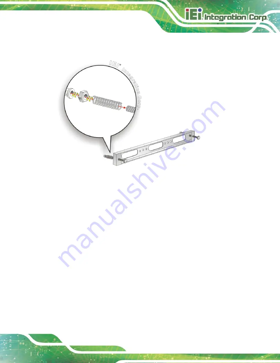
Step 5:
Repeat
Step 4
to install the other three screws into the sides of the two panel
mounting brackets.
Figure 3-16: Panel Mounting Kit Installation
Step 6:
Align the panel mounting bracket screw holes with the VESA mounting holes on
the rear of the panel PC.
Step 7:
Secure the two panel mounting brackets to the rear of the panel PC by inserting
the four retention screws into the VESA mounting holes and tightening them
S
te
p
0
:
Summary of Contents for AFL3-12C-ULT3
Page 2: ...AFL3 12C ULT3 Panel PC Page II Revision Date Version Changes May 7 2018 1 00 Initial release...
Page 16: ......
Page 17: ...AFL3 12C ULT3 Panel PC Page 1 1 Introduction Chapter 1...
Page 26: ...AFL3 12C ULT3 Panel PC Page 10 2 Unpacking Chapter 2...
Page 31: ...AFL3 12C ULT3 Panel PC Page 15 3 Installation Chapter 3...
Page 61: ...AFL3 12C ULT3 Panel PC Page 45 4 BIOS Setup Chapter 4...
Page 95: ...AFL3 12C ULT3 Panel PC Page 79 5 System Maintenance Chapter 5...
Page 100: ...AFL3 12C ULT3 Panel PC Page 84 6 Interface Connectors Chapter 6...
Page 119: ...AFL3 12C ULT3 Panel PC Page 103 Appendix A A Regulatory Compliance...
Page 125: ...AFL3 12C ULT3 Panel PC Page 109 B Safety Precautions Appendix B...
Page 131: ...AFL3 12C ULT3 Panel PC Page 115 C BIOS Menu Options Appendix C...
Page 134: ...AFL3 12C ULT3 Panel PC Page 118 Appendix D D Watchdog Timer...
Page 137: ...AFL3 12C ULT3 Panel PC Page 121 Appendix E E Hazardous Materials Disclosure...


