AFL3-W07A-BT Panel PC
Page 4
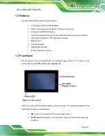
Solid green:
the system is turned on.
1.4 Rear Panel
The rear panel provides access to retention screw holes that support VESA mounting.
See
Figure 1-3: Rear View
1.5 Bottom Panel
The bottom panel of the AFL3-W07A-BT has the following connectors and switches
(
):
1 x 9 V ~ 30 V DC input power jack
2 x RS-232 DB-9 connector
2 x GbE RJ-45 connector
2 x USB 3.2 Gen 1 (5Gb/s) connector
1 x AT/ATX switch
1 x Power button
1 x Reset button
Summary of Contents for AFL3-W07A-BT-N1/PC/2G-R20
Page 13: ...AFL3 W07A BT Panel PC Page 1 1 Introduction Chapter 1 ...
Page 21: ...AFL3 W07A BT Panel PC Page 9 2 Unpacking Chapter 2 ...
Page 25: ...AFL3 W07A BT Panel PC Page 13 3 Installation Chapter 3 ...
Page 54: ...AFL3 W07A BT Panel PC Page 42 4 BIOS Setup Chapter 4 ...
Page 82: ...AFL3 W07A BT Panel PC Page 70 5 System Maintenance Chapter 5 ...
Page 88: ...AFL3 W07A BT Panel PC Page 76 6 Interface Connectors Chapter 6 ...
Page 99: ...AFL3 W07A BT Panel PC Page 87 Appendix A A Regulatory Compliance ...
Page 104: ...AFL3 W07A BT Panel PC Page 92 B Safety Precautions Appendix B ...
Page 109: ...AFL3 W07A BT Panel PC Page 97 C BIOS Menu Options Appendix C ...
Page 112: ...AFL3 W07A BT Panel PC Page 100 Appendix D D Watchdog Timer ...
Page 115: ...AFL3 W07A BT Panel PC Page 103 E Hazardous Materials Disclosure Appendix E ...

