AFL3-W07A-BT Panel PC
Page 78
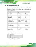
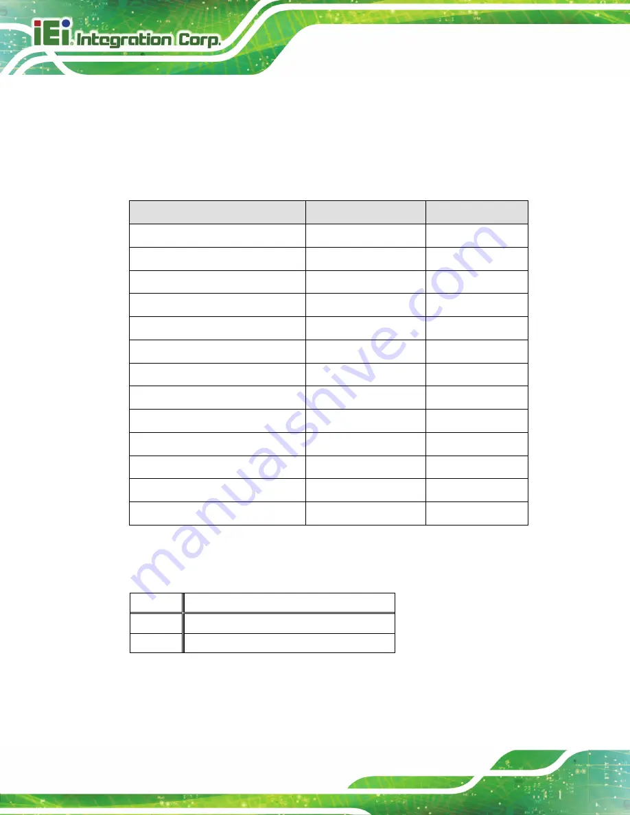
6.2 Internal Peripheral Connectors
Internal peripheral connectors are found on the motherboard and are only accessible
when the motherboard is outside of the chassis. The table below shows a list of the
peripheral interface connectors on the AFL3MB1-BT. Pinouts of these connectors can be
found in the following sections.
Connector
Type
Label
Battery connector
2-pin wafer
BAT1
Debug port
12-pin wafer
DBG_PORT1
LVDS connector
40-pin FPC
LVDS2
MCU connector
6-pin wafer
JSPI2
PCIe Mini card slot
Full-size PCIe Mini slot M_PCIE1
PCIe Mini card slot
Half-size PCIe Mini slot M_PCIE2
Power LED connector
3-pin wafer
PW_LED1
Speaker connector
4-pin wafer
CN3
SPI Flash connector
6-pin wafer
JSPI1
Touch panel connector
8-pin FPC
TOUCH_USB1
USB 2.0 connector
8-pin header
HUB_USB1
VGA connector
10-pin header
VGA_CON1
Webcam connector
4-pin wafer
CAM_USB1
Table 6-1: Peripheral Interface Connectors
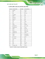
6.2.1 Battery Connector (CN2)
PIN NO.
DESCRIPTION
1
+3V
2
GND
Table 6-2: Battery Connector (CN2) Pinouts
Summary of Contents for AFL3-W07A-BT-N1/PC/2G-R20
Page 13: ...AFL3 W07A BT Panel PC Page 1 1 Introduction Chapter 1 ...
Page 21: ...AFL3 W07A BT Panel PC Page 9 2 Unpacking Chapter 2 ...
Page 25: ...AFL3 W07A BT Panel PC Page 13 3 Installation Chapter 3 ...
Page 54: ...AFL3 W07A BT Panel PC Page 42 4 BIOS Setup Chapter 4 ...
Page 82: ...AFL3 W07A BT Panel PC Page 70 5 System Maintenance Chapter 5 ...
Page 88: ...AFL3 W07A BT Panel PC Page 76 6 Interface Connectors Chapter 6 ...
Page 99: ...AFL3 W07A BT Panel PC Page 87 Appendix A A Regulatory Compliance ...
Page 104: ...AFL3 W07A BT Panel PC Page 92 B Safety Precautions Appendix B ...
Page 109: ...AFL3 W07A BT Panel PC Page 97 C BIOS Menu Options Appendix C ...
Page 112: ...AFL3 W07A BT Panel PC Page 100 Appendix D D Watchdog Timer ...
Page 115: ...AFL3 W07A BT Panel PC Page 103 E Hazardous Materials Disclosure Appendix E ...

