AFL3-W07A-BT-N1 Panel PC
Page 79
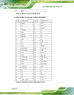
3 NC
4 NC
5 DATA3+
6 DATA3-
7 GND
8 +3.3V
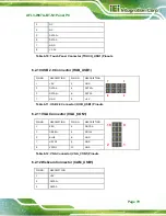
Table 6-10: Touch Panel Connector (TOUCH_USB1) Pinouts
6.2.10 USB 2.0 Connector (HUB_USB1)
PIN NO.
DESCRIPTION
PIN NO.
DESCRIPTION
1 +5V
2 GND
3 DATA4- 4 DATA3+
5 DATA4+ 6 DATA3-
7 GND
8 +5V
7
1
8
2
Table 6-11: USB 2.0 Connector (HUB_USB1) Pinouts
6.2.11 VGA Connector (VGA_CON1)
PIN NO.
DESCRIPTION
PIN NO.
DESCRIPTION
1 RED
2 DDCDA
3 GREEN 4 DDCLK
5 BLUE
6 GND
7 HSYNC 8 GND
9 VSYNC 10
GND
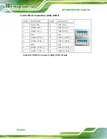
10
9
2
1
Table 6-12: VGA Connector (VGA_CON1) Pinouts
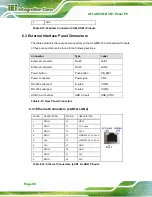
6.2.12 Webcam Connector (CAM_USB1)
PIN NO.
DESCRIPTION
1 +5V
2 DATA2+
3 DATA2-
Summary of Contents for AFL3-W07A-BT-N1
Page 12: ......
Page 13: ...AFL3 W07A BT N1 Panel PC Page 1 1 Introduction Chapter 1...
Page 17: ...AFL3 W07A BT N1 Panel PC Page 5 Figure 1 4 Bottom Panel...
Page 21: ...AFL3 W07A BT N1 Panel PC Page 9 2 Unpacking Chapter 2...
Page 25: ...AFL3 W07A BT N1 Panel PC Page 13 3 Installation Chapter 3...
Page 50: ...AFL3 W07A BT N1 Panel PC Page 38 4 BIOS Setup Chapter 4...
Page 78: ...AFL3 W07A BT N1 Panel PC Page 66 5 System Maintenance Chapter 5...
Page 84: ...AFL3 W07A BT N1 Panel PC Page 72 6 Interface Connectors Chapter 6...
Page 95: ...AFL3 W07A BT N1 Panel PC Page 83 A Safety Precautions Appendix A...
Page 100: ...AFL3 W07A BT N1 Panel PC Page 88 B BIOS Menu Options Appendix B...
Page 103: ...AFL3 W07A BT N1 Panel PC Page 91 Appendix C C Watchdog Timer...
Page 106: ...AFL3 W07A BT N1 Panel PC Page 94 D Hazardous Materials Disclosure Appendix D...


