background image


AFL3-W15C/W19C-ULT3 Panel PC

Page 38 


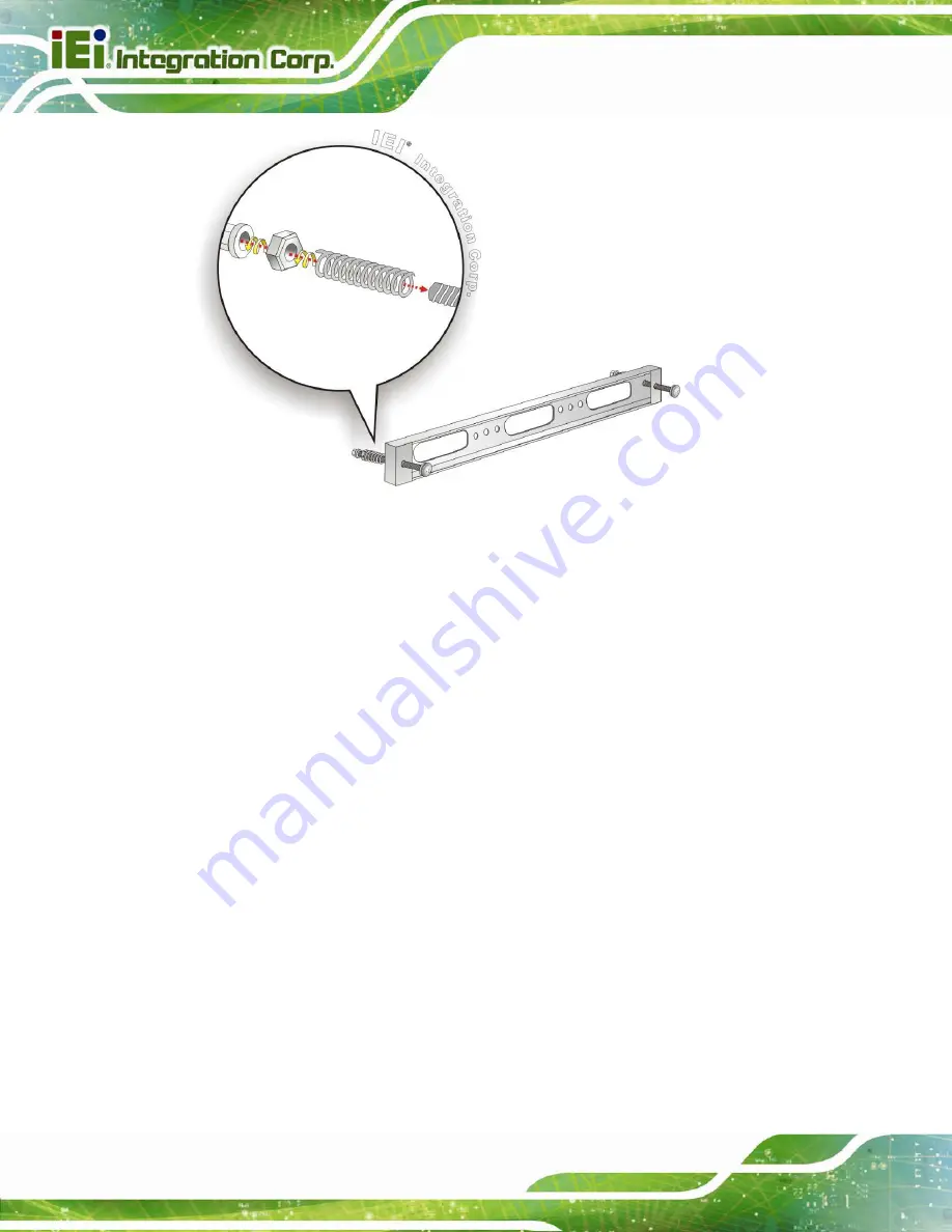
Figure 3-26: Panel Mounting Kit Installation 


Step 6: 

Align the panel mounting bracket screw holes with the VESA mounting holes on 

the rear of the panel PC. 

Step 7: 

Secure the two panel mounting brackets to the rear of the panel PC by inserting 

the four retention screws into the VESA mounting holes and tightening them 

(

Figure 3-27

).

S

te

p

 0

:


Summary of Contents for AFL3-W15C-ULT3

Page 1: ...I User Manual AFL3 W15C W19C ULT3 MODEL Flat Bezel Panel PC with Intel Core i5 6300U Celeron 3955U CPU Touchscreen Four USB 3 0 Dual GbE LAN RS 232 422 485 HD Audio Wi Fi 802 11a b g n ac and RoHS Rev...

Page 2: ...AFL3 W15C W19C ULT3 Panel PC Page II Revision Date Version Changes November 1 2016 1 00 Initial release...

Page 3: ...erheating do not operate it in an area that exceeds the maximum operating temperature described in the user manual Vorsicht Um eine berhitzung des Systems zu vermeiden betreiben Sie es ausschlie lich...

Page 4: ...uso di un altro tipo di adattatore pu causare rischio d incendio o esplosione Si prega di fare riferimento al manuale utente per le specifiche sull alimentazione Atenci n Utilice solamente el adaptado...

Page 5: ...ges arising out of the use or inability to use the product or documentation even if advised of the possibility of such damages This document contains proprietary information protected by copyright All...

Page 6: ...UTION Cautionary messages should be heeded to help reduce the chance of losing data or damaging the product NOTE These messages inform the reader of essential but non critical information These messag...

Page 7: ...wall please follow the steps below Step 1 Select the location on the wall for the wall mounting bracket Step 2 Carefully mark the locations of the four screw holes in the bracket on the wall Step 3 D...

Page 8: ...mount kit into the four screw holes on the real panel of the flat bezel panel PC and tighten until the screw shank is secured against the rear panel Figure 3 22 WARNING Please use the M4 screws provid...

Page 9: ...tly pull the monitor downwards until the monitor rests securely in the slotted holes Figure 3 22 Ensure that all four of the mounting screws fit snugly into their respective slotted holes NOTE In the...

Page 10: ...he AFL3 W15C W19C ULT3 flat bezel panel PC into a panel please follow the steps below Step 1 Select the position on the panel to mount the panel PC Step 2 Cut out a section corresponding to the size s...

Page 11: ...of the panel mounting bracket Then install the following components onto the screw in sequence See Figure 3 26 Sequence Item Photo Instruction 1 Spring Install a spring onto the screw 2 Nut Tighten a...

Page 12: ...Align the panel mounting bracket screw holes with the VESA mounting holes on the rear of the panel PC Step 7 Secure the two panel mounting brackets to the rear of the panel PC by inserting the four r...

Page 13: ...5C W19C ULT3 Panel PC Page 39 Figure 3 27 Securing Panel Mounting Brackets NOTE The panel mounting kit described in this section is an optional item To purchase it please contact an IEI sales represen...

Page 14: ...C ULT3 is installed Step 1 Slide the rear chassis of the AFL3 W15C W19C ULT3 panel PC through the rack cabinet bracket until the frame is flush against the front of the bracket Step 2 Insert a M5 50 s...

Page 15: ...Step 4 Align the rack mounting bracket screw holes with the VESA mounting holes on the rear of the panel PC Step 5 Secure the two rack mounting brackets to the rear of the panel PC by inserting the fo...

Page 16: ...W19C ULT3 Panel PC Page 42 Figure 3 29 Securing Rack Mounting Brackets Step 6 Slide the panel PC with the attached rack cabinet bracket into a rack or cabinet Figure 3 30 Figure 3 30 Install into a Ra...

Page 17: ...he AFL3 W15C W19C ULT3 on an arm please follow the steps below Step 1 The arm is a separately purchased item Please correctly mount the arm onto the surface it uses as a base To do this refer to the i...

Page 18: ...e 3 31 Arm Mounting Retention Screw Holes Step 4 Secure the AFL3 W15C W19C ULT3 to the interface pad by inserting four retention screws through the mounting arm interface pad and into the AFL3 W15C W1...

Page 19: ...the steps below Step 1 Locate the screw holes on the rear of the AFL3 W15C W19C ULT3 This is where the bracket will be attached Step 2 Align the bracket with the screw holes Step 3 To secure the brack...

Reviews: