AFL3-W15C/W19C/W22C-ULT3 Panel PC
Page 34
3.8 DB-9 Serial Port Pin 9 Selection
Pin 9 on the COM1 and COM2 DB-9 connectors can be set as the ring (RI) signal, +5 V or
+12 V. The jumper selection options are shown in
JP5
Description
Short 1-2
COM1 RI Pin use +12 V
Short 3-4
COM1 RI Pin use RI (Default)
Short 5-6
COM1 RI Pin use +5 V
Table 3-2: COM1 Pin 9 Setting Jumper Settings (JP5)
JP4
Description
Short 1-2
COM2 RI Pin use +12 V
Short 3-4
COM2 RI Pin use RI (Default)
Short 5-6
COM2 RI Pin use +5 V
Table 3-3: COM2 Pin 9 Setting Jumper Settings (JP4)
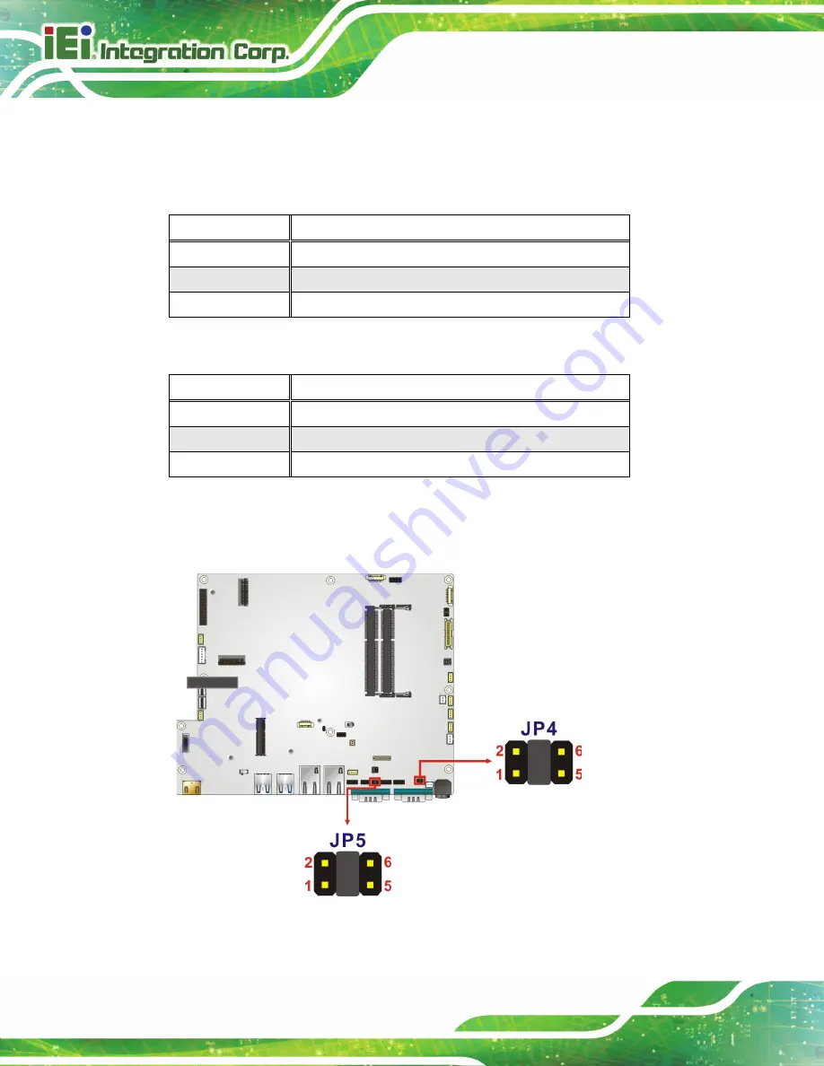
The DB-9 Serial Port Pin 9 Setting jumper locations are shown in
Figure 3-20: DB-9 Serial Port Pin 9 Setting Jumper Locations
Summary of Contents for AFL3-W22C-ULT3
Page 17: ...AFL3 W15C W19C W22C ULT3 Panel PC Page 1 1 Introduction Chapter 1...
Page 30: ...AFL3 W15C W19C W22C ULT3 Panel PC Page 14 2 Unpacking Chapter 2...
Page 35: ...AFL3 W15C W19C W22C ULT3 Panel PC Page 19 3 Installation Chapter 3...
Page 72: ...AFL3 W15C W19C W22C ULT3 Panel PC Page 56 4 BIOS Setup Chapter 4...
Page 107: ...AFL3 W15C W19C W22C ULT3 Panel PC Page 91 5 System Maintenance Chapter 5...
Page 112: ...AFL3 W15C W19C W22C ULT3 Panel PC Page 96 6 Interface Connectors Chapter 6...
Page 131: ...AFL3 W15C W19C W22C ULT3 Panel PC Page 115 Appendix A A Regulatory Compliance...
Page 137: ...AFL3 W15C W19C W22C ULT3 Panel PC Page 121 B Safety Precautions Appendix B...
Page 143: ...AFL3 W15C W19C W22C ULT3 Panel PC Page 127 C BIOS Menu Options Appendix C...
Page 146: ...AFL3 W15C W19C W22C ULT3 Panel PC Page 130 Appendix D D Watchdog Timer...
Page 149: ...AFL3 W15C W19C W22C ULT3 Panel PC Page 133 Appendix E E Hazardous Materials Disclosure...


