background image


AFOKAR-08A-RK39 


Page 5 

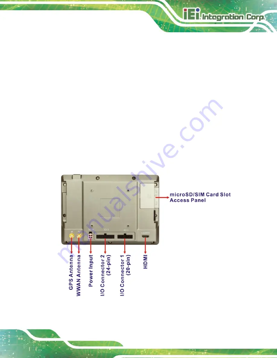
1.4 Rear Panel 

The rear panel has VESA mounting screw holes and an access panel for microSD card 

and SIM card. The following I/O connectors can also be found on the rear panel. 


1 x 9 V~ 30 V DC input connector   


20-pin connector: 

o


1 x OBD-II/J1939   

o


1 x USB 2.0 


24-pin connector: 

o


1 x Audio out   

o


1 x RS-232 

o


1 x RS-485   

o


2-bit digital input and 2-bit digital output 


1 x HDMI output connector   


1 x GPS antenna connector 


1 x WWAN antenna connector   


Figure 1-4: Rear Panel 

Summary of Contents for AFOKAR-08A-RK39

Page 1: ...DEL AFOKAR 08A RK39 8 In Vehicle Android Panel PC with P CAP Touchscreen Rockchip RK3399 on board SoC OBD II GPS HDMI microSD USB 2 0 3 0 RS 232 Wi Fi Bluetooth Camera Digital I O RoHS Compliant IP 54...

Page 2: ...AFOKAR 08A RK39 Page II Revision Date Version Changes October 8 2018 1 00 Initial release...

Page 3: ...ising out of the use or inability to use the product or documentation even if advised of the possibility of such damages This document contains proprietary information protected by copyright All right...

Page 4: ...ury Warnings should be taken seriously CAUTION Cautionary messages should be heeded to help reduce the chance of losing data or damaging the product NOTE These messages inform the reader of essential...

Page 5: ...PTIONAL ITEMS 12 3 INSTALLATION 14 3 1 ANTI STATIC PRECAUTIONS 15 3 2 INSTALLATION PRECAUTIONS 15 3 3 MICROSD CARD INSTALLATION 16 3 4 SIM CARD INSTALLATION OPTIONAL 17 3 5 MOUNTING THE SYSTEM 19 3 6...

Page 6: ...Arranging the Home Screen 35 4 2 NAVIGATION BUTTONS 36 4 3 STATUS BAR 37 A REGULATORY COMPLIANCE 39 B SAFETY PRECAUTIONS 44 B 1 SAFETY PRECAUTIONS 45 B 1 1 General Safety Precautions 45 B 1 2 Anti st...

Page 7: ...les 19 Figure 3 6 IO 1 Connector Pinout Locations 20 Figure 3 7 OBD II Cable 21 Figure 3 8 OBD II Connector Pinouts 21 Figure 3 9 IO 2 Connector Pinout Locations 22 Figure 3 10 HDMI Connector 23 Figur...

Page 8: ...le 1 2 Technical Specifications 9 Table 2 1 Packing List 12 Table 2 2 Optional Items 13 Table 3 1 IO 1 Connector Pinouts 20 Table 3 2 IO 2 Connector Pinouts 22 Table 3 3 HDMI Connector Pinouts 23 Tabl...

Page 9: ...AFOKAR 08A RK39 Page 1 Chapter 1 1 Introduction...

Page 10: ...OBD II connection and GPS functionality make the AFOKAR 08A RK39 an ideal system for in vehicle applications Other peripherals include one USB 3 0 port and two I O connectors which support RS 232 RS48...

Page 11: ...eless connection Optional WWAN connectivity with SIM slot and an external antenna IP 54 compliant front panel Android 7 1 OS pre installed RoHS compliance 1 3 Front Panel The front of the AFOKAR 08A R...

Page 12: ...WAN connection Figure 1 3 LED Indicators Power LED Off The system is turned off Blue The system is turned on Bluetooth LED Off Bluetooth is disabled Blue Bluetooth is enabled Wi Fi LED Off Wi Fi is di...

Page 13: ...ing I O connectors can also be found on the rear panel 1 x 9 V 30 V DC input connector 20 pin connector o 1 x OBD II J1939 o 1 x USB 2 0 24 pin connector o 1 x Audio out o 1 x RS 232 o 1 x RS 485 o 2...

Page 14: ...The top panel has a power button Press the power button for 4 6 seconds to power on the system The bottom panel has a 2 W speaker Figure 1 5 Top and Bottom Panels 1 6 Side Panel The right side panel...

Page 15: ...AFOKAR 08A RK39 Page 7 1 7 Dimensions The dimensions are shown below Figure 1 7 Dimensions unit mm...

Page 16: ...time Clock Battery backup RTC OS Android 7 1 Display LCD 8 TFT LCD with LED backlight Max Resolution 800 x 1280 Brightness cd m2 500 Contrast Ratio 800 1 Pixel Pitch mm 0 13455 W x 0 13455 H Viewing...

Page 17: ...r axis Operating Vibration MIL STD 810F 514 5C 2 IP Level IP 54 compliant front panel Certifications CE FCC e MARK Connectors Buttons and Indicators Antenna Connectors 1 x GPS antenna SMA female conne...

Page 18: ...AFOKAR 08A RK39 Page 10 Chapter 2 2 Unpacking...

Page 19: ...em Step 3 Lift the AFOKAR 08A RK39 out of the boxes Step 4 Take the AFOKAR 08A RK39 out from the plastic bag Step 5 Pull the plastic cover off the AFOKAR 08A RK39 Step 6 Make sure all the components l...

Page 20: ...ng List 2 2 Optional Items The following are optional components which may be separately purchased Item Image Power adapter with transfer cable P N IVIPOWER 4PIN R10 ACC power cable P N 32002 001900 1...

Page 21: ...O connector 1 cable 20 pin P N 32024 003800 100 RS I O connector 2 cable 24 pin P N 32124 004400 100 RS VESA mount stand 138 mm P N IVI MK03 R10 Table 2 2 Optional Items If any of these items are mis...

Page 22: ...AFOKAR 08A RK39 Page 14 Chapter 3 3 Installation...

Page 23: ...p to prevent ESD from damaging the board Self grounding Before handling the board touch any grounded conducting material During the time the board is handled frequently touch any conducting materials...

Page 24: ...3 microSD Card Installation To install the microSD card follow the instructions below Step 1 Remove the retention screw and lift the microSD card slot access panel Figure 3 1 microSD Card Slot Access...

Page 25: ...e with a micro SIM 3FF adapter or a nano SIM 4FF adapter Please install a mini SIM 2FF or Standard SIM card for proper network connection NOTE Before installing a SIM card for WWAN connection please m...

Page 26: ...card slot Figure 3 4 Insert a SIM card into the slot to install it To remove the SIM card push the SIM card to release it Figure 3 4 SIM Card Installation Step 3 Replace and secure the SIM card slot a...

Page 27: ...on screw holes for fastening four M4 6 screws are shown in Figure 3 5 Refer to the installation guide that came with the mounting device to mount the AFOKAR 08A RK39 Figure 3 5 VESA Mount Retention Sc...

Page 28: ...ripheral devices 1 x OBD II J1939 1 x USB 2 0 The pinouts for the IO 1 connector are listed in the figure and table below Figure 3 6 IO 1 Connector Pinout Locations Pin Description Pin Description 1 N...

Page 29: ...ser can purchase the optional OBD II cable Figure 3 7 to connect the AFOKAR 08A RK39 with the vehicle Figure 3 7 OBD II Cable The pinout locations of OBD II cable connector are shown below Figure 3 8...

Page 30: ...listed in the figure and table below Figure 3 9 IO 2 Connector Pinout Locations Pin Description Pin Description RS 232 1 RS232_TXD 13 RS232_RXD RS 232 2 RS232_RTS 14 RS232_CTS 3 GND 15 GND RS 485 4 R...

Page 31: ...the figure and table below Figure 3 10 HDMI Connector PIN NO DESCRIPTION PIN NO DESCRIPTION 1 HDMI_DATA2 2 GND 3 HDMI_DATA2 4 HDMI_DATA1 5 GND 6 HDMI_DATA1 7 HDMI_DATA0 8 GND 9 HDMI_DATA0 10 HDMI_CLK...

Page 32: ...he figure and table below Figure 3 11 Power Input Connector PIN NO DESCRIPTION 1 GND 2 GND 3 POWER 4 ACC Table 3 4 Power Input Connector Pinouts Optional Choice The AFOKAR 08A RK39 can use either ACC...

Page 33: ...Figure 3 13 Figure 3 13 Optional Cigarette Lighter Cable 3 6 5 USB Connector The AFOKAR 08A RK39 has one USB 3 0 port on the right side panel The USB port has a screw on the side for securing the USB...

Page 34: ...use damage to the internal electronic components and may also cause injury to the user To power on the AFOKAR 08A RK39 connect the AFOKAR 08A RK39 to the vehicle through a power cable or connect the s...

Page 35: ...find all the relevant software utilities and documentation Figure 3 15 IEI Resource Download Center 3 8 1 Driver Download To download drivers from IEI Resource Download Center follow the steps below...

Page 36: ...Step 6 Click the driver file name on the page and you will be prompted with the following window You can download the entire ISO file or click the small arrow to find an individual driver and click th...

Page 37: ...il they must be replaced Please contact the system reseller or vendor to purchase the replacement parts NOTE A user cannot replace a motherboard If the motherboard fails it must be shipped back to IEI...

Page 38: ...AFOKAR 08A RK39 Page 30 Chapter 4 4 Android OS...

Page 39: ...upports multiple home screens allowing users to customize the screen with widgets apps and shortcuts The following sections describe the basic technique to manage the home screen 4 1 1 Adding a Home S...

Page 40: ...ens Swipe right or left to switch between home screens Figure 4 2 Multiple Home Screens 4 1 3 Favorites Tray The Favorites tray at the bottom of each home screen allows users to keep the most importan...

Page 41: ...dd app or widget shortcuts on the home screen follow the steps below Step 1 To add an app shortcut tap the up arrow on the home screen to access the All Apps page To add a widget shortcut touch and ho...

Page 42: ...AFOKAR 08A RK39 Page 34 Step 2 Touch and hold an app icon or a widget and drag it to the home screen Figure 4 4 All Apps WIDGETS Page...

Page 43: ...he items on the home screen can be moved and deleted Touch and hold an item on the home screen and drag it where you want To trash the item on the screen drag it to the Remove icon Release the icon wh...

Page 44: ...at the bottom of every screen Figure 4 6 Navigation Buttons Buttons Description Tap to turn the volume down Tap to return to the previous screen Tap to return to the home screen Tap to display all th...

Page 45: ...tatus Bar The status bar on the top of the screen Figure 4 9 displays system status such as battery level or signal strength Figure 4 7 Status Bar Swipe down from the status bar to view notification a...

Page 46: ...AFOKAR 08A RK39 Page 38 Figure 4 8 Notification List and System Status...

Page 47: ...AFOKAR 08A RK39 Page 39 Appendix A A Regulatory Compliance...

Page 48: ...with the essential requirements and other relevant provisions of Directive 2014 53 EU Bulgarian IEI Integration Corp 2014 53 EU esky Czech IEI Integration Corp t mto prohla uje e tento za zen je ve sh...

Page 49: ...ietuvi Lithuanian IEI Integration Corp deklaruoja kad is ranga atitinka esminius reikalavimus ir kitas 2014 53 EU Direktyvos nuostatas Nederlands Dutch IEI Integration Corp dat het toestel toestel in...

Page 50: ...direktive 2014 53 EU Slovensky Slovak IEI Integration Corp t mto vyhlasuje e zariadenia sp a z kladn po iadavky a v etky pr slu n ustanovenia Smernice 2014 53 EU Suomi Finnish IEI Inte ration Corp vak...

Page 51: ...ence at his own expense Federal Communication Commission Interference Statement This equipment has been assembled with components that comply with the limits for a Class B digital device pursuant to P...

Page 52: ...AFOKAR 08A RK39 Page 44 B Safety Precautions Appendix B...

Page 53: ...risk of electric shock make sure power cord is unplugged from wall socket To fully disengage the power to the unit please disconnect the power cord from the power outlet Refer servicing to qualified...

Page 54: ...luding the AFOKAR 08A RK39 Dry climates are especially susceptible to ESD It is therefore critical that whenever the AFOKAR 08A RK39 is opened and any of the electrical components are handled the foll...

Page 55: ...lassified as electronic device in terms of the European Directive 2012 19 EU WEEE and must not be disposed of as domestic garbage EU wide legislation as implemented in each Member State requires that...

Page 56: ...any other components To clean the LCD panel gently wipe it with a piece of soft dry cloth or a slightly moistened cloth The interior of the device does not require cleaning Keep fluids away from the d...

Page 57: ...as they may damage the plastic parts Vacuum cleaner Using a vacuum specifically designed for computers is one of the best methods of cleaning the device Dust and dirt can restrict the airflow in the...

Page 58: ...AFOKAR 08A RK39 Page 50 Appendix C C Hazardous Materials Disclosure...

Page 59: ...These components will be separately marked Please refer to the following table Part Name Toxic or Hazardous Substances and Elements Lead Pb Mercury Hg Cadmium Cd Hexavalent Chromium CR VI Polybrominat...

Page 60: ...RK39 Page 52 RoHS RoHS Pb Hg Cd CR VI PBB PBDE O O O O O O O O O O O O O O O O O O O O O O O O O O O O O O O O O O O O O O O O O O O O O O O O O SJ T 11363 2006 GB T 26572 2011 X SJ T 11363 2006 GB T...

Reviews: