AFOKAR-08A-RK39
Page 20
3.6 External I/O Connectors
This section provides an overview of the external I/O connectors of the
AFOKAR-08A-RK39.
3.6.1 I/O Connector 1 (20-pin)
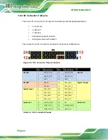
The 20-pin I/O connector (IO 1) supports the following external peripheral devices:
1 x OBD-II/J1939
1 x USB 2.0
The pinouts for the IO 1 connector are listed in the figure and table below.
Figure 3-6: IO 1 Connector Pinout Locations
Pin
Description
Pin
Description
1
NC
11
NC
2
NC
12
NC
3
NC
13
USB VCC (+5V)
USB 2.0
4
NC
14
USB DATA-
5
NC
15
USB DATA+
OBD-II
6
J2
16
GND
7
J2850_BUS-
17
NC
8
GND
18
GND
OBD-II
9
OBD_CAN_H
19
ISO-9141-2-K
10
OBD_CAN_L
20
ISO-9141-2-L
Table 3-1: IO 1 Connector Pinouts
Summary of Contents for AFOKAR-08A
Page 2: ...AFOKAR 08A RK39 Page II Revision Date Version Changes October 8 2018 1 00 Initial release ...
Page 9: ...AFOKAR 08A RK39 Page 1 Chapter 1 1 Introduction ...
Page 18: ...AFOKAR 08A RK39 Page 10 Chapter 2 2 Unpacking ...
Page 22: ...AFOKAR 08A RK39 Page 14 Chapter 3 3 Installation ...
Page 38: ...AFOKAR 08A RK39 Page 30 Chapter 4 4 Android OS ...
Page 46: ...AFOKAR 08A RK39 Page 38 Figure 4 8 Notification List and System Status ...
Page 47: ...AFOKAR 08A RK39 Page 39 Appendix A A Regulatory Compliance ...
Page 52: ...AFOKAR 08A RK39 Page 44 B Safety Precautions Appendix B ...
Page 58: ...AFOKAR 08A RK39 Page 50 Appendix C C Hazardous Materials Disclosure ...

