5
Step 6: Connect cables and additional I/O ports
. Connect the power button cable,
the power LED cable and the power connector cable (BRICK-NANO/WAFER series
only) to the corresponding connectors on the SBC (refer to the QIG that came with the
SBC for detailed information).
If there are additional I/O connectors to be installed on the front panel, connect them
to the corresponding connectors on the motherboard now.
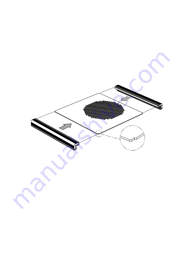
Step 7: Assemble edge bars to top panel
. Align the slot of the edge bar with the
edge of the top panel, and assemble the edge bar to the side of the top panel.
Please
note the direction of the corner notches as shown below.
-----------------------------------------------------------------------------------------------------------------
NOTE:
For the BRICK-NANO/WAFER series, the SATA cable from the installed HDD must be
connected to the SATA connector and SATA power connector on the SBC before
installing the top panel to the chassis.
-----------------------------------------------------------------------------------------------------------------
Step 8: Install top panel to chassis
. Orient the top panel to position the ventilation
vents right above the CPU heat sink. Place the top panel together with the two edge
bars onto the top of chassis. Ensure both side panels fit into the slot of the edge bars.
Secure the top panel to the chassis with two screws (flat head, M3*6, black) into the
rear panel.


