DRPC-120-BTi Embedded System
Page 93
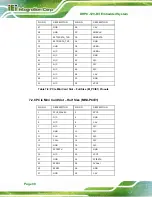
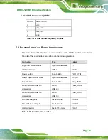
7.2.13 USB Connector (USB1)
PIN NO.
DESCRIPTION
1 VCC
2 USB_DATA-
3
4 GND
Table 7-14: USB Connector (USB1) Pinouts
7.3 External Interface Panel Connectors
The table below lists the rear panel connectors on the DRPC-120-BTi motherboard.
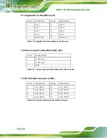
Pinouts of these connectors can be found in the following sections.
Connector
Type
Label
Digital I/O terminal block
5-pin terminal block
J1
HDMI connector
HDMI
HDMI1
Power button
Push button
PWR_BTN1
Power input terminal block
3-pin terminal block
DC_IN1
Reset button
Push button
RST_BTN1
RJ-45 LAN and USB 2.0
connectors
RJ-45,
USB 2.0
LAN2_USB2
RJ-45 LAN and USB 3.0
connectors
RJ-45,
USB 3.0
LAN1_USB1
RS-232 serial ports
D-sub 9 male
COM1/2
RS-422/485 serial ports
D-sub 9 male
COM3/4
VGA connector
D-sub 15 female
VGA1
Table 7-15: Rear Panel Connectors
Summary of Contents for DRPC-120-BT
Page 12: ......
Page 13: ...DRPC 120 BTi Embedded System Page 1 Chapter 1 1 Introduction...
Page 23: ...DRPC 120 BTi Embedded System Page 11 Chapter 2 2 Unpacking...
Page 28: ...DRPC 120 BTi Embedded System Page 16 Chapter 3 3 Installation...
Page 49: ...DRPC 120 BTi Embedded System Page 37 Chapter 4 4 System Maintenance...
Page 53: ...DRPC 120 BTi Embedded System Page 41 Chapter 5 5 BIOS...
Page 86: ...DRPC 120 BTi Embedded System Page 74 Chapter 6 6 Programming OLED for DRPC 120 BTi E5 OLED...
Page 97: ...DRPC 120 BTi Embedded System Page 85 Chapter 7 7 Interface Connectors...
Page 110: ...DRPC 120 BTi Embedded System Page 98 Appendix A A Safety Precautions...
Page 115: ...DRPC 120 BTi Embedded System Page 103 Appendix B B Digital I O Interface...
Page 118: ...DRPC 120 BTi Embedded System Page 106 Appendix C C Hazardous Materials Disclosure...


