DRPC-120-BTi Embedded System
Page 21
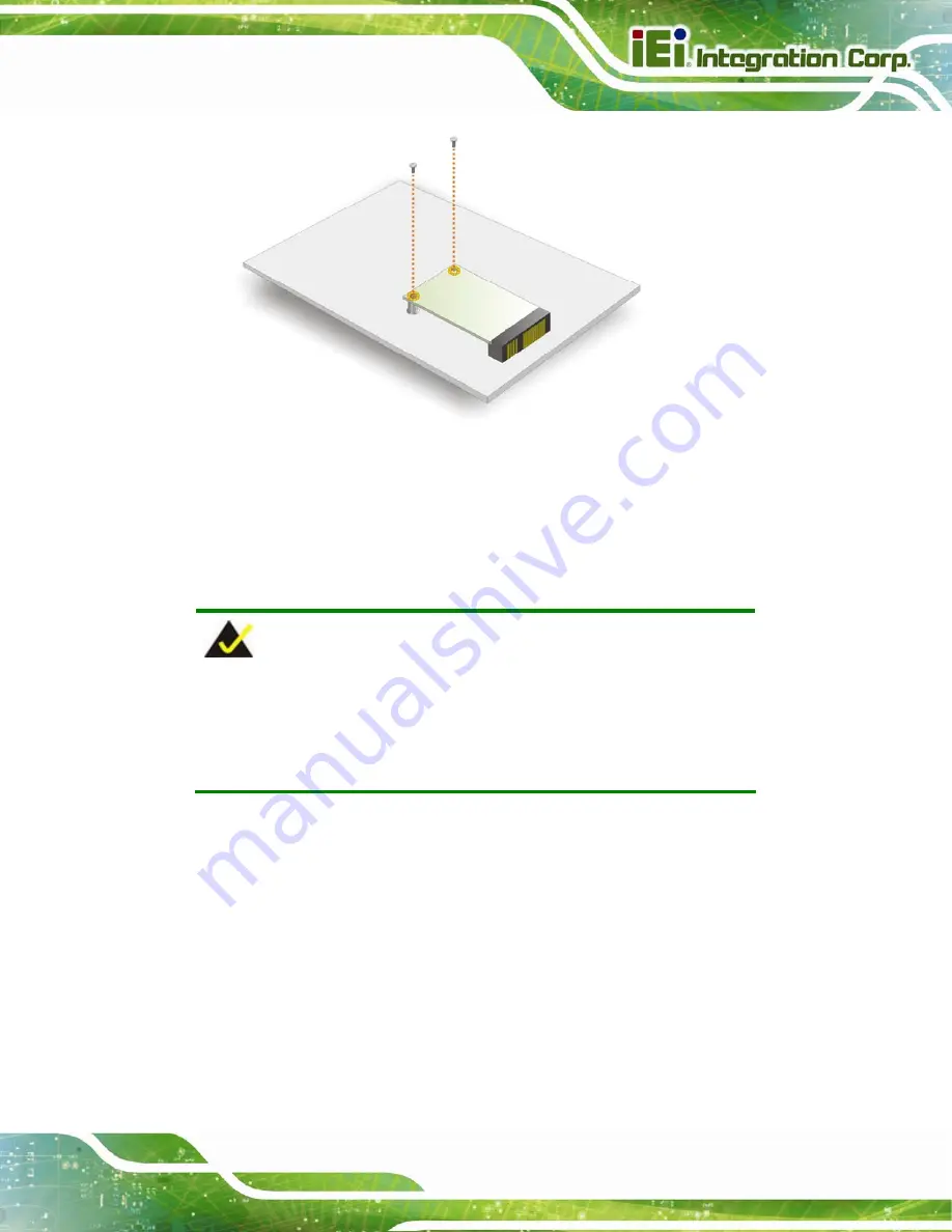
Figure 3-5: Securing the PCIe Mini Card
Step 5:
Replace and secure the internal access panel to the system.
Step 0:
3.5 IPMI Module Installation (Optional)
NOTE:
The IPMI module slot is designed to install the IEI iRIS-2400 IPMI 2.0
module only. DO NOT install other modules into the IPMI module slot.
Doing so may cause damage to the DRPC-120-BTi.
Please follow the steps below to install the iRIS-2400 module, and refer to
Section 3.10
for the setup procedure.
Step 1:
Remove the internal access panel from the DRPC-120-BTi. Please follow the
instruction described in
.
Step 2:
Locate the IPMI module slot on the motherboard (
Summary of Contents for DRPC-120-BT
Page 12: ......
Page 13: ...DRPC 120 BTi Embedded System Page 1 Chapter 1 1 Introduction...
Page 23: ...DRPC 120 BTi Embedded System Page 11 Chapter 2 2 Unpacking...
Page 28: ...DRPC 120 BTi Embedded System Page 16 Chapter 3 3 Installation...
Page 49: ...DRPC 120 BTi Embedded System Page 37 Chapter 4 4 System Maintenance...
Page 53: ...DRPC 120 BTi Embedded System Page 41 Chapter 5 5 BIOS...
Page 86: ...DRPC 120 BTi Embedded System Page 74 Chapter 6 6 Programming OLED for DRPC 120 BTi E5 OLED...
Page 97: ...DRPC 120 BTi Embedded System Page 85 Chapter 7 7 Interface Connectors...
Page 110: ...DRPC 120 BTi Embedded System Page 98 Appendix A A Safety Precautions...
Page 115: ...DRPC 120 BTi Embedded System Page 103 Appendix B B Digital I O Interface...
Page 118: ...DRPC 120 BTi Embedded System Page 106 Appendix C C Hazardous Materials Disclosure...


