DRPC-124-EHL
Page 18
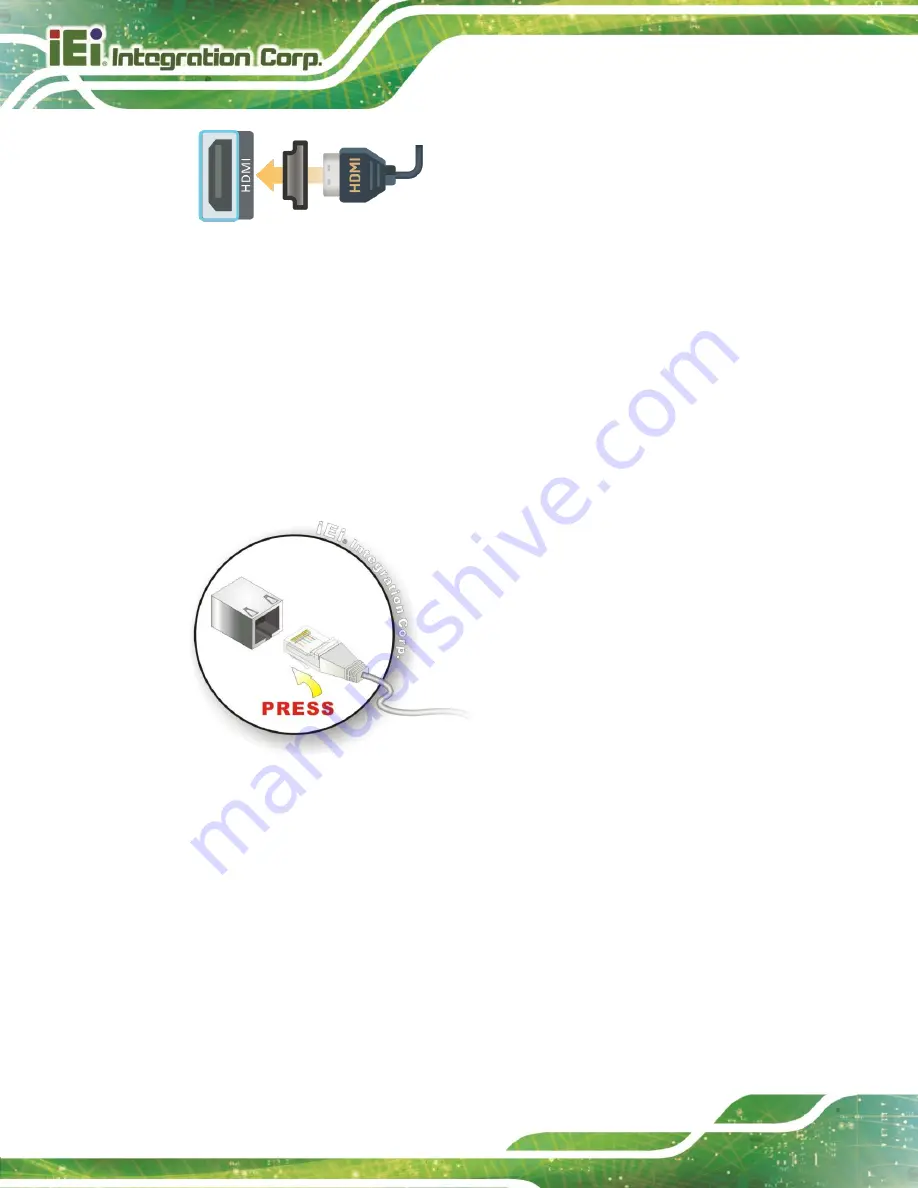
Figure 3-9: HDMI Connection
3.7.2
LAN Connectors
The LAN connectors allow connection to an external network
Step 1:
Locate the RJ-45 connectors.
The locations of the RJ-45 connectors are shown
in
Chapter 1
Step 2:
Align the connectors. Align the RJ-45 connector on the LAN cable with one of the
RJ-45 connectors on the
DRPC-124-EHL
Series. See
Figure 3-10: LAN Connection
Step 3:
Insert the LAN cable RJ-45 connector. Once aligned, gently insert the LAN cable
RJ-45 connector into the on-board RJ-45 connector
The RJ-45 Ethernet connector has two status LEDs, one green and one yellow. The green
LED indicates activity on the port and the yellow LED indicates the port is linked.
Summary of Contents for DRPC-124-EHL Series
Page 12: ......
Page 13: ...DRPC 124 EHL Page 1 Chapter 1 1 Introduction...
Page 18: ...DRPC 124 EHL Page 6 Chapter 2 2 Unpacking...
Page 22: ...DRPC 124 EHL Page 10 Chapter 3 3 Installation...
Page 36: ...DRPC 124 EHL Page 24 Chapter 4 4 System Motherboard...
Page 61: ...DRPC 124 EHL Page 49 Chapter 5 5 BIOS...
Page 101: ...DRPC 124 EHL Page 89 Appendix A A Regulatory Compliance...
Page 103: ...DRPC 124 EHL Page 91 Appendix B B Product Disposal...
Page 105: ...DRPC 124 EHL Page 93 Appendix C C Error Beep Code...
Page 107: ...DRPC 124 EHL Page 95 Appendix D D Hazardous Materials Disclosure...


