background image


EBC-3620                                IEI Technology Corp.                             Page  7 
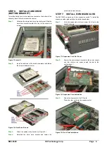
 

Step 4: 

Fasten the expansion card retention screw. 

Figure 20: Expansion Card Retention Screw 
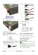
Step 5: 

Optionally attach the expansion screw cover and 

fasten the two screws. 

Step 0:


Figure 21: Expansion Card Screw Cover 
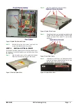
STEP 8: 

FRONT PANEL CABLES 

The following buttons, LEDs and USB port are on the front panel of 
the EBC-3620 chassis. 


1 x Power LED 

1 x HDD LED 

1 x Power switch 

1 x Reset button 

2 x USB ports 

1 x Backplane ATX connector 

 
These components are all connected to the CPU card with cables. 
To correctly connect these cables, please refer to the technical 
documentation that came with your CPU card. The connectors that 
are provided with the chassis are listed below. 
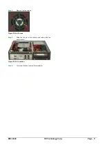
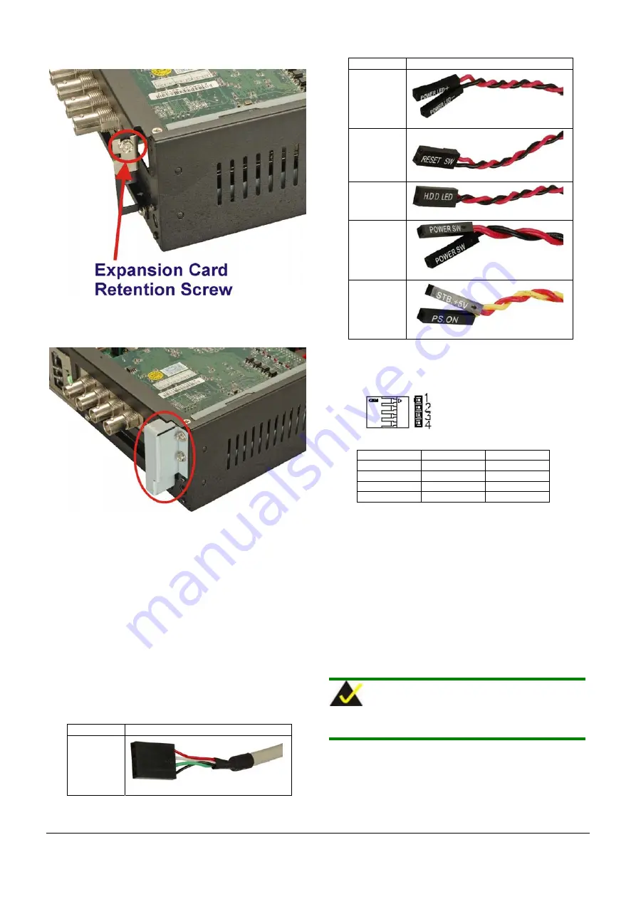
 

No. Name 

USB cable   

No. Name 

Power LED cable 

Reset Switch cable 

HDD LED cable 

Power switch cable 

Backplane ATX connector cable 

Table 3: Chassis Connectors 

 
USB cable pin definitions are shown below 


PIN No. 

Description 

Color 

+5V Red 

D- White 

D+ Green 

GND Black 

Table 4: USB Cable Pinouts 


STEP 9: 

COVER REINSTALLATION 

Cover reinstallation is in the reverse order of removal. 

Step 1: 

Position the internal support bracket and fasten the 
screw. 

Step 2: 

Reinstall cover and fasten the two screws.


Step 0:


CHASSIS MAINTENANCE 


F

AN 

R

EPLACEMENT 


 NOTE: 

Please ensure that the power of the computer is switched off before 
fan replacement procedure. 

 
There are two cooling fans inside the EBC-3620 chassis. To replace 
them, please follow the instructions below. 

Step 1: 

Open the chassis (refer to Figure 2) 

Summary of Contents for EBC-3620

Page 1: ...ion o 5 17Hz 0 1 double amplitude displacement o 17 640Hz 1 5G acceleration peak to peak Shock 10G acceleration peak to peak Drive Bay Combinations Listed in Table 1 below Optical Drives Expansion Car...

Page 2: ...EBC 3620 IEI Technology Corp Page 2 DIMENSION DRAWING EBC 3620 dimensions are shown below Figure 1 Dimension Drawing measurement in millimeters...

Page 3: ...PPORT BRACKET REMOVAL The top cover is secured to the chassis with six retention screws three on each side of the chassis To remove the top cover please follow the steps below Step 1 Remove the two to...

Page 4: ...nto the optical drive bracket Slide the optical drive from the front of the bracket Figure 7 Slide the Optical Drive Step 2 Attach the optical drive screws and tighten Figure 8 Optical Drive Screws St...

Page 5: ...ves in the main hard drive bracket follow the instructions below Step 1 Undo the hard drive bracket screws indicated below Figure 12 Hard Drive Bracket Screws Step 2 Remove the hard drive bracket from...

Page 6: ...ch the cables to the hard drive Figure 14 Step 4 Reinstall the hard drive bracket and fasten the previously removed screw Step 0 STEP 7 INSTALL EXPANSION CARD The EBC 3620 supports up to two expansion...

Page 7: ...onnectors that are provided with the chassis are listed below No Name 2 USB cable No Name 1 Power LED cable 1 Reset Switch cable 1 HDD LED cable 1 Power switch cable 1 Backplane ATX connector cable Ta...

Page 8: ...ology Corp Page 8 Step 2 Remove the fan screws Figure 22 Fan Screws Step 3 Slide the fan out of the chassis and remove the fan power cable Figure 23 Fan Location Step 4 To reinstall the fan reverse th...

Reviews: