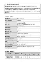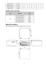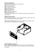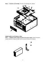
IEI SUPPORT URL
https://new.ieiworld.com/en/online_support_form/index.php
COMPLIANCE
This equipment has been tested and found to comply with specifications for CE marking. If the user modifies
and/or installs other devices in the equipment, the CE conformity declaration may no longer apply.
This equipment complies with Part 15 of the FCC Rules. Operation is subject to the following two conditions:
This device may not cause harmful interference, and
This device must accept any interference received, including interference that may cause
undesired operation.
This equipment has been tested and found to comply with the limits for a Class A digital device, pursuant to
part 15 of the FCC Rules. These limits are designed to provide reasonable protection against harmful
interference when the equipment is operated in a commercial environment. This equipment generates, uses,
and can radiate radio frequency energy and, if not installed and used in accordance with the instruction
manual, may cause harmful interference to radio communications. Operation of this equipment in a
residential area is likely to cause harmful interference in which case the user will be required to correct the
interference at his own expense.
According to the requirement of the WEEE legislation the following user information is provided to customers
for all branded IEI Electronics products subject to the WEEE directive.
This symbol on the product or on its packaging indicates that this product must not be disposed of with your
other household waste. Instead, it is your responsibility to dispose of your waste equipment by handing it over
to a designated collection point for the recycling of waste electrical and electronic equipment. The separate
collection and recycling of your waste equipment at the time of disposal will help to conserve natural
resources and ensure that it is recycled in a manner that protects human health and the environment. For
more information about where you can drop o- your waste equipment for recycling, please contact your local
city office, your household waste disposal service or the shop where you purchased the product.
Headquarters
威強電工業電腦股份有限公司
IEI Integration Corp.
22161
新北市汐止區中興路
29
號
No. 29, Zhongxing Rd., Xizhi Dist.,
New Taipei City 22161, Taiwan
TEL: +886-2-86886-2-26902098
FAX: +886-2-66160028
sales@ieiworld.com
www.ieiworld.com
America
IEI Technology USA Corp.
138 University Parkway, Pomona,
CA 91768, USA
Tel:+1-909-595-2819
Fax:+1-909-595-2816
sales@usa.ieiworld.com
usa.ieiworld.com
China
威强电工业电脑
IEI Integration (Shanghai) Corp.
上海市闵行莘庄工业区申富路
515
号
No. 515, Shen Fu Rd., Xin Zhuang Industrial
Develop Zone, Shanghai, 201108, China
Tel:+86-21-3116-7799
Fax:+86-21-3462-7797
sales@ieiworld.com.cn
www.ieiworld.com.cn
Copyright ©2019 IEI Integration Corp. All rights reserved
Summary of Contents for ECA-200
Page 10: ...9...


