


ECN-780-Q67 Em b e d d e d S ys te m
P a g e ix
Lis t o f Fig u re s
Figure 1-2: ECN-780-Q67 Front Panel
........................................................................................... 5
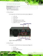
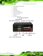
Figure 1-3: ECN-780-Q67 Rear Panel
............................................................................................ 6
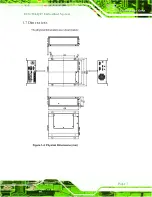
Figure 1-4: Physical Dimensions (mm)
........................................................................................ 7
Figure 3-1: Retention Screws Removal
......................................................................................14
Figure 3-3: HDD Retention Screws
.............................................................................................15
Figure 3-4: AT/ATX Switch Location
...........................................................................................16
Figure 3-5: Reset Button Location
..............................................................................................17
Figure 3-6: Power Button Location
.............................................................................................18
Figure 3-7: Mounting Screw Holes
..............................................................................................18
Figure 3-8: Mounting Bracket Retention Screws
......................................................................19
Figure 3-9: Peripheral Connectors (Front Panel)
......................................................................21
Figure 3-10: Peripheral Connectors (Rear Panel)
.....................................................................21
Figure 3-15: DB-9 Serial Port Connector
....................................................................................26
Figure 3-16: USB Device Connection
.........................................................................................27
Figure 4-1: Connector and Jumper Locations (Front Side)
.....................................................31
Figure 4-2: Connector and Jumper Locations (Rear Side)
.......................................................32
Figure 4-3: Motherboard Dimensions (Front Side) (mm)
..........................................................32
Figure 4-4: Motherboard Dimensions (Rear Side) (mm)
...........................................................33
Figure 4-5: Battery Connector Location
.....................................................................................35
Figure 4-6: BIOS Programming Connector Location
................................................................36
Figure 4-7: Digital I/O Connector Location
................................................................................37
Figure 4-8: EC Programming Connector Location
....................................................................38
Figure 4-9: System Fan Connector Location
.............................................................................39
Summary of Contents for ECN-780-Q67
Page 14: ...ECN 780 Q67 Embedded Sys tem Page 1 Chapter 1 1 Introduction...
Page 21: ...ECN 780 Q67 Embedded Sys tem Page 8 Chapter 2 2 Unpacking...
Page 25: ...ECN 780 Q67 Embedded Sys tem Page 12 Chapter 3 3 Ins tallation...
Page 43: ...ECN 780 Q67 Embedded Sys tem Page 30 Chapter 4 4 Sys tem Motherboard...
Page 69: ...ECN 780 Q67 Embedded Sys tem Page 56 Chapter 5 5 BIOS...
Page 106: ...ECN 780 Q67 Embedded Sys tem Page 93 6 Software Drivers Chapter 5...
Page 128: ...ECN 780 Q67 Embedded Sys tem Page 115 Figure 6 32 Intel ME Driver Installation Finish Screen...
Page 129: ...ECN 780 Q67 Embedded Sys tem Page 116 A Safety Precautions Appendix A...
Page 134: ...ECN 780 Q67 Embedded Sys tem Page 121 B BIOS Menu Options Appendix B...
Page 137: ...ECN 780 Q67 Embedded Sys tem Page 124 Appendix C C One Key Recovery...
Page 145: ...ECN 780 Q67 Embedded Sys tem Page 132 Figure C 5 Partition Creation Commands...
Page 178: ...ECN 780 Q67 Embedded Sys tem Page 165 D Watchdog Timer Appendix D...
Page 181: ...ECN 780 Q67 Embedded Sys tem Page 168 Appendix E E Hazardous Materials Dis clos ure...


