ECW-281B/B2-D525 Embedded System
Page 25
PIN NO. DESCRIPTION
1 GND
2 TX+
3 TX-
4 GND
5 RX-
6 RX+
7 GND
Table 3-9: SATA Drive Connector Pinouts
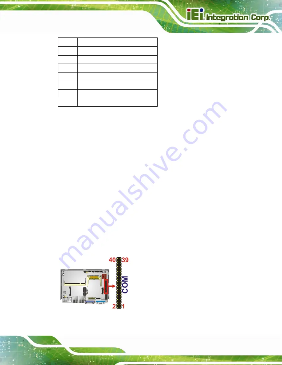
3.3.9 Serial Port Connector (COM3, COM4, COM5 and COM6)
CN Label:
COM
CN Type:
40-pin header (2x20)
CN Location:
The 40-pin serial port connector contains the following four serial ports: COM3, COM4,
COM5 and COM6. All these serial ports are RS-232 serial communications channels. The
serial port locations are specified below.
COM3 is located on pin 1 to pin 10
COM4 is located on pin 11 to pin 20
COM5 is located on pin 21 to pin 30
COM6 is located on pin 31 to pin 40
Figure 3-10: COM3 to COM6 Connector Pinout Locations
Summary of Contents for ECW-281B-D525
Page 13: ...ECW 281B B2 D525 Embedded System Page 1 Chapter 1 1 Introduction ...
Page 20: ...ECW 281B B2 D525 Embedded System Page 8 Chapter 2 2 Mechanical Description ...
Page 26: ...ECW 281B B2 D525 Embedded System Page 14 Chapter 3 3 System Components ...
Page 41: ...ECW 281B B2 D525 Embedded System Page 29 Chapter 4 4 Installation ...
Page 61: ...ECW 281B B2 D525 Embedded System Page 49 Figure 4 20 Power Button ...
Page 62: ...ECW 281B B2 D525 Embedded System Page 50 5 BIOS Chapter 6 ...
Page 91: ...ECW 281B B2 D525 Embedded System Page 79 Chapter 6 6 Troubleshooting and Maintenance ...
Page 97: ...ECW 281B B2 D525 Embedded System Page 85 A Safety Precautions Appendix A ...
Page 102: ...ECW 281B B2 D525 Embedded System Page 90 B BIOS Menu Options Appendix B ...
Page 105: ...ECW 281B B2 D525 Embedded System Page 93 C Watchdog Timer Appendix C ...


