ECW-281B/B2-D525 Embedded System
Page 15
3.1 Embedded System Motherboard
NOTE:
The jumpers and connectors shown in the section below are those jumpers
and connectors that are relevant to the configuration and installation of the
embedded system. For a complete list of jumpers and connectors on the
WAFER-PV-D5252 motherboard, please refer to the WAFER-PV-D5252 user
manual.
The ECW-281B/B2-D525 models have a WAFER-PV-D5252 motherboard installed in the
system. The following sections describe the relevant connectors and jumpers on the
motherboard.
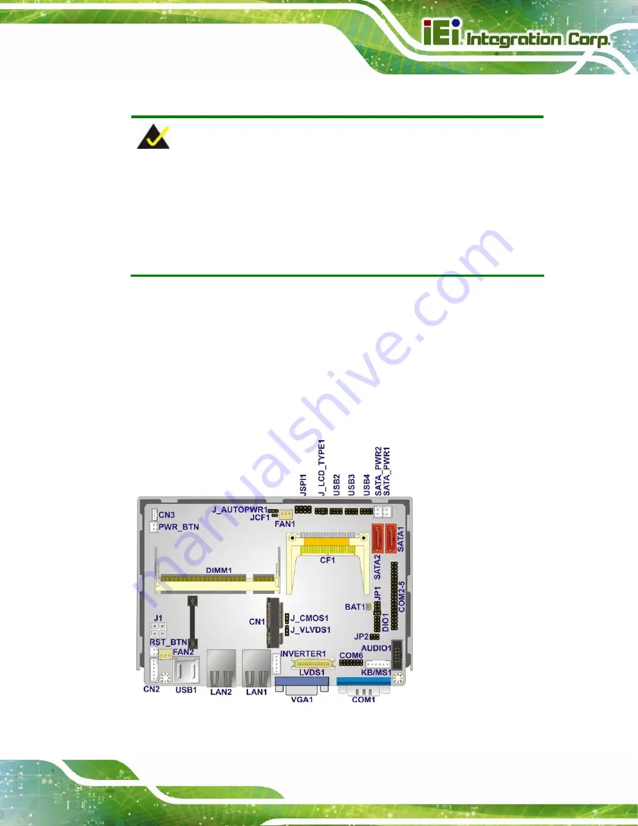
3.1.1 WAFER-PV-D5252 Motherboard Overview
The locations of the WAFER-PV-D5252 jumpers and connectors used on the
ECW-281B/B2-D525 are shown in
654
Figure 3-1: WAFER-PV-D5252 Jumper and Connector Locations
Summary of Contents for ECW-281B-D525
Page 13: ...ECW 281B B2 D525 Embedded System Page 1 Chapter 1 1 Introduction ...
Page 20: ...ECW 281B B2 D525 Embedded System Page 8 Chapter 2 2 Mechanical Description ...
Page 26: ...ECW 281B B2 D525 Embedded System Page 14 Chapter 3 3 System Components ...
Page 41: ...ECW 281B B2 D525 Embedded System Page 29 Chapter 4 4 Installation ...
Page 61: ...ECW 281B B2 D525 Embedded System Page 49 Figure 4 20 Power Button ...
Page 62: ...ECW 281B B2 D525 Embedded System Page 50 5 BIOS Chapter 6 ...
Page 91: ...ECW 281B B2 D525 Embedded System Page 79 Chapter 6 6 Troubleshooting and Maintenance ...
Page 97: ...ECW 281B B2 D525 Embedded System Page 85 A Safety Precautions Appendix A ...
Page 102: ...ECW 281B B2 D525 Embedded System Page 90 B BIOS Menu Options Appendix B ...
Page 105: ...ECW 281B B2 D525 Embedded System Page 93 C Watchdog Timer Appendix C ...


