ECW-281B/B2-D525 Embedded System
Page 28
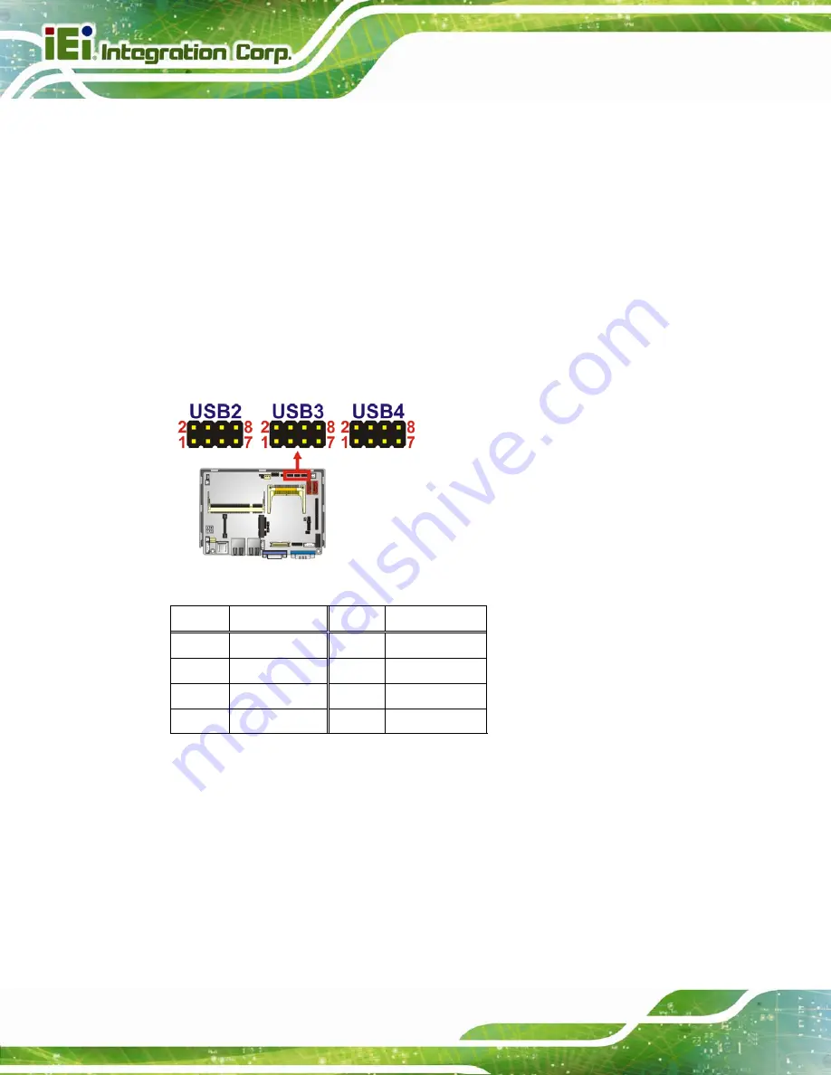
3.3.11 USB Connectors (Internal)
CN Label:
USB4
CN Type:
8-pin header (2x4)
CN Location:
CN Pinouts:
The 2x4 USB pin connectors each provide connectivity to two USB 1.1 or two USB 2.0
ports. Each USB connector can support two USB devices. Additional external USB ports
are found on the rear panel. The USB ports are used for I/O bus expansion.
Figure 3-12: USB Connector Pinout Locations
PIN NO. DESCRIPTION PIN NO. DESCRIPTION
1 VCC
2 GND
3 DATA-
4 DATA+
5 DATA+ 6 DATA-
7 GND
8 VCC
Table 3-12: USB Port Connector Pinouts
Summary of Contents for ECW-281B-D525
Page 13: ...ECW 281B B2 D525 Embedded System Page 1 Chapter 1 1 Introduction ...
Page 20: ...ECW 281B B2 D525 Embedded System Page 8 Chapter 2 2 Mechanical Description ...
Page 26: ...ECW 281B B2 D525 Embedded System Page 14 Chapter 3 3 System Components ...
Page 41: ...ECW 281B B2 D525 Embedded System Page 29 Chapter 4 4 Installation ...
Page 61: ...ECW 281B B2 D525 Embedded System Page 49 Figure 4 20 Power Button ...
Page 62: ...ECW 281B B2 D525 Embedded System Page 50 5 BIOS Chapter 6 ...
Page 91: ...ECW 281B B2 D525 Embedded System Page 79 Chapter 6 6 Troubleshooting and Maintenance ...
Page 97: ...ECW 281B B2 D525 Embedded System Page 85 A Safety Precautions Appendix A ...
Page 102: ...ECW 281B B2 D525 Embedded System Page 90 B BIOS Menu Options Appendix B ...
Page 105: ...ECW 281B B2 D525 Embedded System Page 93 C Watchdog Timer Appendix C ...


