E-265-GM45/EP-267-GM45 Enrich POS System
Page 6
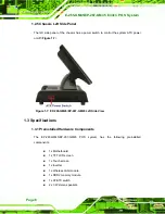
1.2.3.1 I/O Interface Panel
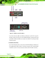
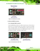
The I/O interface panel located on the right side of the monitor (see
has
the following I/O interface connectors:
1 x Serial port connector (COM1)
1 x 12 V PoweredUSB connector
2 x USB 2.0 connectors
1 x COM port power selecting switch (12 V / 5V)
The external I/O interface connectors on the rear side of the monitor are shown in
Figure 1-5: I/O Interface Connectors on the Monitor Right Side Panel
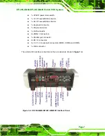
1.2.4 I/O Interface Panel
The I/O interface panel is located on the rear side of the EP-265-GM45/EP-267-GM45
chassis and protected by an easily-removed cover (
has the following I/O interface connectors:
1 x 12 V or 24 V DC In connector
1 x 12 V DC Out connector
Summary of Contents for EP-265-GM45
Page 13: ...EP 265 GM45 EP 267 GM45 Enrich POS System Page 1 1 Introduction Chapter 1...
Page 24: ...E 265 GM45 EP 267 GM45 Enrich POS System Page 12 2 Detailed Specifications Chapter 2...
Page 39: ...EP 265 GM45 EP 267 GM45 Enrich POS System Page 27 3 Unpacking Chapter 3...
Page 42: ...E 265 GM45 EP 267 GM45 Enrich POS System Page 30 4 Installation Chapter 4...
Page 64: ...E 265 GM45 EP 267 GM45 Enrich POS System Page 52 5 System Maintenance Chapter 4...
Page 70: ...E 265 GM45 EP 267 GM45 Enrich POS System Page 58 6 AMI BIOS Setup Chapter 6...
Page 113: ...EP 265 GM45 EP 267 GM45 Enrich POS System Page 101 7 System Monitoring Chapter 7...
Page 116: ...E 265 GM45 EP 267 GM45 Enrich POS System Page 104 A System Specifications Appendix A...
Page 122: ...E 265 GM45 EP 267 GM45 Enrich POS System Page 110 B External Connector Pinouts Appendix B...
Page 125: ...EP 265 GM45 EP 267 GM45 Enrich POS System Page 113 C Safety Precautions Appendix C...
Page 129: ...EP 265 GM45 EP 267 GM45 Enrich POS System Page 117 D BIOS Configuration Options Appendix D...
Page 133: ...EP 265 GM45 EP 267 GM45 Enrich POS System Page 121 E Watchdog Timer Appendix E...
Page 136: ...E 265 GM45 EP 267 GM45 Enrich POS System Page 124 F Hazardous Materials Disclosure Appendix F...


