EP-265-GM45/EP-267-GM45 Enrich POS System
Page 33
Step 0:
4.5 Remove the Bottom Panels
To access the CF slot and HDD slot, the bottom panels must be removed. To remove the
bottom panels, please follow the steps below.
Step 1:
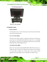
Adjust the monitor (
) and turn the EP-265-GM45/EP-267-GM45 over
to put the monitor front panel on the table.
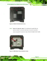
Figure 4-1: Monitor Adjustment
Step 2:
Remove the bottom panels
. Remove the five retention screws (
from the bottom panel and lift the two bottom panels off the
EP-265-GM45/EP-267-GM45.
Step 0:
Summary of Contents for EP-265-GM45
Page 13: ...EP 265 GM45 EP 267 GM45 Enrich POS System Page 1 1 Introduction Chapter 1...
Page 24: ...E 265 GM45 EP 267 GM45 Enrich POS System Page 12 2 Detailed Specifications Chapter 2...
Page 39: ...EP 265 GM45 EP 267 GM45 Enrich POS System Page 27 3 Unpacking Chapter 3...
Page 42: ...E 265 GM45 EP 267 GM45 Enrich POS System Page 30 4 Installation Chapter 4...
Page 64: ...E 265 GM45 EP 267 GM45 Enrich POS System Page 52 5 System Maintenance Chapter 4...
Page 70: ...E 265 GM45 EP 267 GM45 Enrich POS System Page 58 6 AMI BIOS Setup Chapter 6...
Page 113: ...EP 265 GM45 EP 267 GM45 Enrich POS System Page 101 7 System Monitoring Chapter 7...
Page 116: ...E 265 GM45 EP 267 GM45 Enrich POS System Page 104 A System Specifications Appendix A...
Page 122: ...E 265 GM45 EP 267 GM45 Enrich POS System Page 110 B External Connector Pinouts Appendix B...
Page 125: ...EP 265 GM45 EP 267 GM45 Enrich POS System Page 113 C Safety Precautions Appendix C...
Page 129: ...EP 265 GM45 EP 267 GM45 Enrich POS System Page 117 D BIOS Configuration Options Appendix D...
Page 133: ...EP 265 GM45 EP 267 GM45 Enrich POS System Page 121 E Watchdog Timer Appendix E...
Page 136: ...E 265 GM45 EP 267 GM45 Enrich POS System Page 124 F Hazardous Materials Disclosure Appendix F...

