EP-265-GM45/EP-267-GM45 Enrich POS System
Page 57
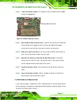
Step 4:
Locate the wireless module
. The wireless module is located below the DIMM
sockets. See
.
Figure 5-3: Wireless Module Location
Step 5:
Open the Mini PCIe socket arm clips
. The Mini PCIe socket has two clips that
secure the Mini PCIe wireless module into the socket. Before the wireless
module can be removed from the socket, the clips must be opened.
Step 6:
Remove the wireless module
. Once the two clips of the Mini PCIe socket are
open, remove the wireless module from the socket.
Step 7:
Align the new wireless module with the Mini PCIe socket
. The wireless
module must be oriented in such a way that the notch in the wireless module
must be aligned with the plastic bridge in the socket.
Step 8:
Insert the wireless module
. Push the wireless module into the socket at an
angle.
Step 9:
Secure the wireless module
. Push the wireless module down until the two
clips into place, securing the card in place.
5.4.5 Motherboard Replacement
A user cannot replace a motherboard. If the motherboard fails it must be shipped back to
IEI to be replaced. If the system motherboard has failed, please contact the system vendor,
reseller or an IEI sales person directly.
Summary of Contents for EP-265-GM45
Page 13: ...EP 265 GM45 EP 267 GM45 Enrich POS System Page 1 1 Introduction Chapter 1...
Page 24: ...E 265 GM45 EP 267 GM45 Enrich POS System Page 12 2 Detailed Specifications Chapter 2...
Page 39: ...EP 265 GM45 EP 267 GM45 Enrich POS System Page 27 3 Unpacking Chapter 3...
Page 42: ...E 265 GM45 EP 267 GM45 Enrich POS System Page 30 4 Installation Chapter 4...
Page 64: ...E 265 GM45 EP 267 GM45 Enrich POS System Page 52 5 System Maintenance Chapter 4...
Page 70: ...E 265 GM45 EP 267 GM45 Enrich POS System Page 58 6 AMI BIOS Setup Chapter 6...
Page 113: ...EP 265 GM45 EP 267 GM45 Enrich POS System Page 101 7 System Monitoring Chapter 7...
Page 116: ...E 265 GM45 EP 267 GM45 Enrich POS System Page 104 A System Specifications Appendix A...
Page 122: ...E 265 GM45 EP 267 GM45 Enrich POS System Page 110 B External Connector Pinouts Appendix B...
Page 125: ...EP 265 GM45 EP 267 GM45 Enrich POS System Page 113 C Safety Precautions Appendix C...
Page 129: ...EP 265 GM45 EP 267 GM45 Enrich POS System Page 117 D BIOS Configuration Options Appendix D...
Page 133: ...EP 265 GM45 EP 267 GM45 Enrich POS System Page 121 E Watchdog Timer Appendix E...
Page 136: ...E 265 GM45 EP 267 GM45 Enrich POS System Page 124 F Hazardous Materials Disclosure Appendix F...

