FLEX-BX100-ULT5
Page 25
3.8 Mounting the System
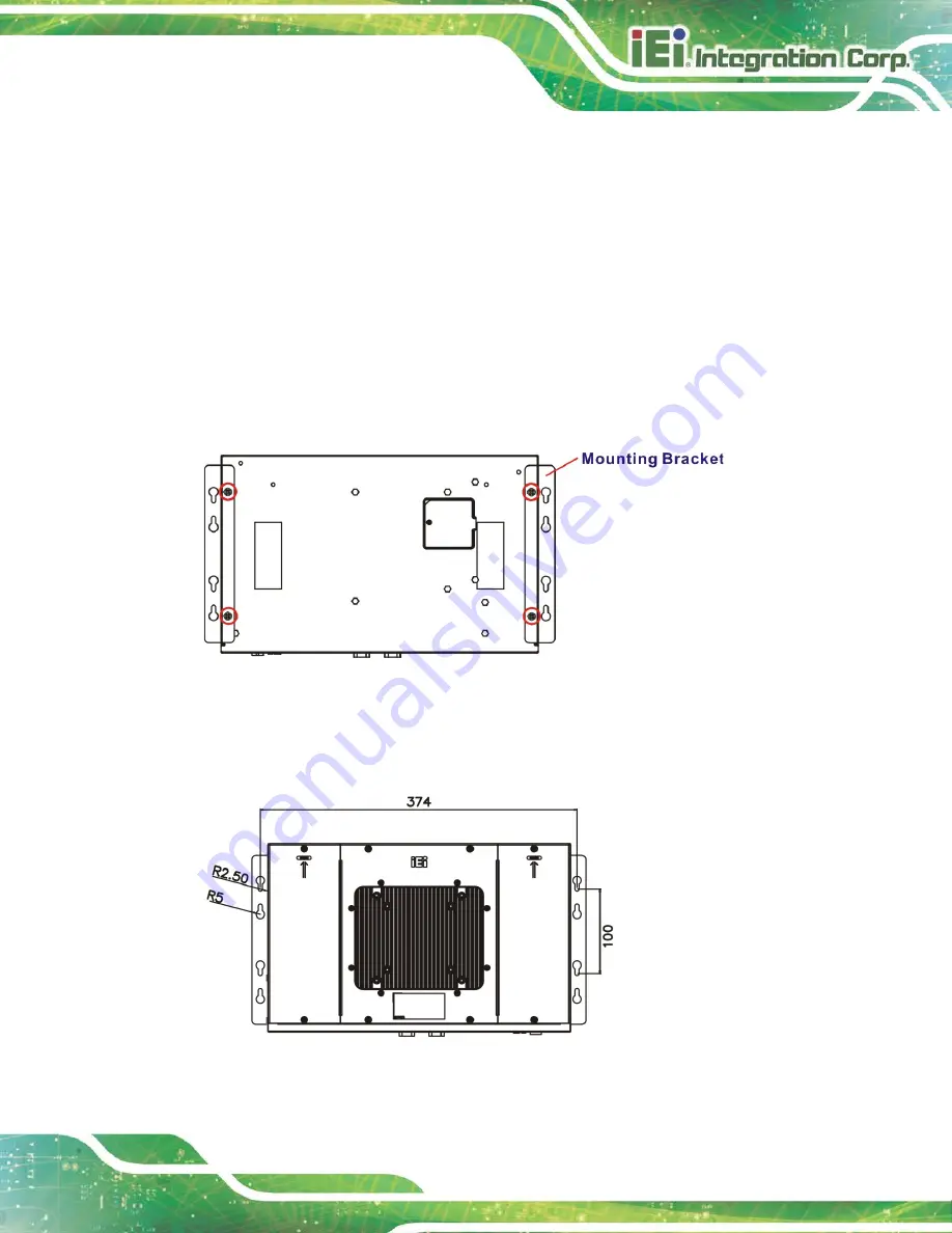
To mount only the box PC onto a wall or some other surface using the two mounting
brackets, please follow the steps below.
Step 1:
Turn the box PC over.
Step 2:
Align the two retention screw holes in each bracket with the retention screw
holes on the sides of the bottom surface.
Step 3:
Secure the brackets to the system by inserting two retention screws (M4*6) into
each bracket (
Figure 3-18: Mounting Bracket Retention Screws
Step 4:
Drill holes in the intended installation surface according to the bracket
dimensions listed below.
Figure 3-19: Mounting Bracket Retention Screws
Summary of Contents for FLEX-BX100-ULT5
Page 2: ...FLEX BX100 ULT5 Page ii Revision Date Version Changes January 14 2021 1 00 Initial release...
Page 12: ...FLEX BX100 ULT5 Page xii Figure 6 1 Main Board Layout Diagram 73...
Page 15: ...FLEX BX100 ULT5 Page 1 Chapter 1 1 Introduction...
Page 23: ...FLEX BX100 ULT5 Page 9 Chapter 2 2 Unpacking...
Page 27: ...FLEX BX100 ULT5 Page 13 Chapter 3 3 Installation...
Page 47: ...FLEX BX100 ULT5 Page 33 Chapter 4 4 BIOS...
Page 82: ...FLEX BX100 ULT5 Page 68 Chapter 5 5 Troubleshooting and Maintenance...
Page 86: ...FLEX BX100 ULT5 Page 72 6 Interface Connectors Chapter 6...
Page 100: ...FLEX BX100 ULT5 Page 86 Appendix A A Regulatory Compliance...
Page 105: ...FLEX BX100 ULT5 Page 91 B Safety Precautions Appendix B...
Page 111: ...FLEX BX100 ULT5 Page 97 Appendix C C BIOS Menu Options...
Page 114: ...FLEX BX100 ULT5 Page 100 Appendix D D Watchdog Timer...
Page 117: ...FLEX BX100 ULT5 Page 103 Appendix E E Error Beep Code...
Page 119: ...FLEX BX100 ULT5 Page 105 Appendix F F Hazardous Materials Disclosure...


