FLEX-BX100-ULT5
Page 29
3.12 Power-On Procedure
3.12.1 Installation Checklist
WARNING:
Make sure a power supply with the correct input voltage is being fed into
the system. Incorrect voltages applied to the system may cause damage to
the internal electronic components and may also cause injury to the user.
To power on the box PC please make sure of the following:
The top covers are installed
All peripheral devices are connected
The power cables are plugged in
The system is securely mounted
3.12.2 Power-on Procedure
To power-on the FLEX-BX100-ULT5 please follow the steps below:
Step 1:
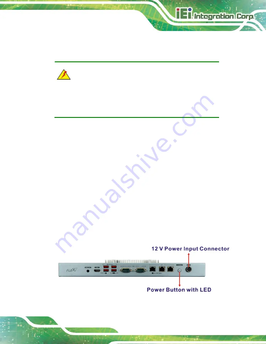
Connect the power source to the power inlet on the front panel.
Ensure to
connect the power cord to a socket-outlet with earthing connection.
Step 2:
Press the power button on the front panel until the LED lights on in blue to power
up the system (
).
Step 0:
Figure 3-23: Power Button
Summary of Contents for FLEX-BX100-ULT5
Page 2: ...FLEX BX100 ULT5 Page ii Revision Date Version Changes January 14 2021 1 00 Initial release...
Page 12: ...FLEX BX100 ULT5 Page xii Figure 6 1 Main Board Layout Diagram 73...
Page 15: ...FLEX BX100 ULT5 Page 1 Chapter 1 1 Introduction...
Page 23: ...FLEX BX100 ULT5 Page 9 Chapter 2 2 Unpacking...
Page 27: ...FLEX BX100 ULT5 Page 13 Chapter 3 3 Installation...
Page 47: ...FLEX BX100 ULT5 Page 33 Chapter 4 4 BIOS...
Page 82: ...FLEX BX100 ULT5 Page 68 Chapter 5 5 Troubleshooting and Maintenance...
Page 86: ...FLEX BX100 ULT5 Page 72 6 Interface Connectors Chapter 6...
Page 100: ...FLEX BX100 ULT5 Page 86 Appendix A A Regulatory Compliance...
Page 105: ...FLEX BX100 ULT5 Page 91 B Safety Precautions Appendix B...
Page 111: ...FLEX BX100 ULT5 Page 97 Appendix C C BIOS Menu Options...
Page 114: ...FLEX BX100 ULT5 Page 100 Appendix D D Watchdog Timer...
Page 117: ...FLEX BX100 ULT5 Page 103 Appendix E E Error Beep Code...
Page 119: ...FLEX BX100 ULT5 Page 105 Appendix F F Hazardous Materials Disclosure...


