


gKINO-DMF SBC
Page 20
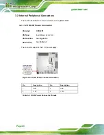
3.2 Internal Peripheral Connectors
The section describes all of the connectors on the gKINO-DMF.
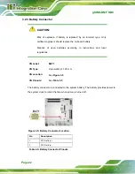
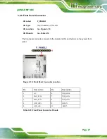
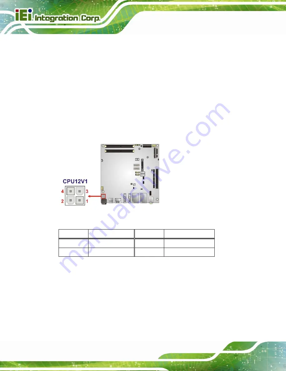
3.2.1 12 V DC-IN Power Connector
CN Label:
CPU12V1
CN Type:
4-pin Molex, p=4.2 mm
CN Location:
CN Pinouts:
The connector supports the 12 V power supply.
Figure 3-3: DC-IN Power Connector Location
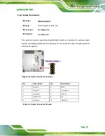
Pin Description Pin Description
1 GND
2 GND
3 +12V
4 +12V
Table 3-3: DC-IN Power Connector Pinouts
Summary of Contents for gKINO-DMF-216-R10
Page 2: ...gKINO DMF SBC Page II Revision Date Version Changes June 29 2017 1 00 Initial release ...
Page 14: ......
Page 15: ...gKINO DMF SBC Page 1 Chapter 1 1 Introduction ...
Page 19: ...gKINO DMF SBC Page 5 Figure 1 3 Connectors Solder Side ...
Page 25: ...gKINO DMF SBC Page 11 Chapter 2 2 Unpacking ...
Page 29: ...gKINO DMF SBC Page 15 Chapter 3 3 Connectors ...
Page 31: ...gKINO DMF SBC Page 17 Figure 3 2 Connector and Jumper Locations Rear ...
Page 63: ...gKINO DMF SBC Page 49 Chapter 4 4 Installation ...
Page 77: ...gKINO DMF SBC Page 63 Chapter 5 5 BIOS ...
Page 112: ...gKINO DMF SBC Page 98 Chapter 6 6 Software Drivers ...
Page 115: ...gKINO DMF SBC Page 101 Appendix A A Regulatory Compliance ...
Page 117: ...gKINO DMF SBC Page 103 B Product Disposal Appendix B ...
Page 119: ...gKINO DMF SBC Page 105 Appendix C C BIOS Menu Options ...
Page 122: ...gKINO DMF SBC Page 108 Appendix D D Terminology ...
Page 126: ...gKINO DMF SBC Page 112 Appendix E E Digital I O Interface ...
Page 129: ...gKINO DMF SBC Page 115 Appendix F F Watchdog Timer ...
Page 132: ...gKINO DMF SBC Page 118 Appendix G G Hazardous Materials Disclosure ...


