HTB-100-HM170 Medical Box PC
Page 30
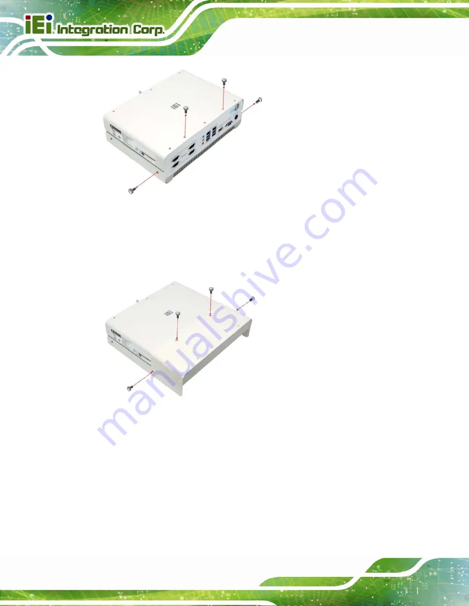
Figure 3-22: Side Screws Removal
Step 2:
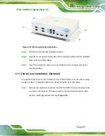
Secure the cable cover to the HTB-100-HM170 with four retention screws
(
). Ensure to secure the two top panel screws in the slot (not the
large opening) of the keyhole in the cable cover.
Step 0:
Figure 3-23: Cable Cover Installation
Summary of Contents for HTB-100-HM170
Page 14: ......
Page 15: ...HTB 100 HM170 Medical Box PC Page 1 Chapter 1 1 Introduction...
Page 22: ...HTB 100 HM170 Medical Box PC Page 8 Chapter 2 2 Unpacking...
Page 26: ...HTB 100 HM170 Medical Box PC Page 12 Chapter 3 3 Installation...
Page 49: ...HTB 100 HM170 Medical Box PC Page 35 Chapter 4 4 BIOS...
Page 91: ...HTB 100 HM170 Medical Box PC Page 77 Chapter 5 5 Troubleshooting and Maintenance...
Page 97: ...HTB 100 HM170 Medical Box PC Page 83 Chapter 6 6 Interface Connectors...
Page 112: ...HTB 100 HM170 Medical Box PC Page 98 Appendix A A Regulatory Compliance...
Page 117: ...HTB 100 HM170 Medical Box PC Page 103 B Safety Precautions Appendix B...
Page 123: ...HTB 100 HM170 Medical Box PC Page 109 Appendix C C BIOS Menu Options...
Page 126: ...HTB 100 HM170 Medical Box PC Page 112 Appendix D D Watchdog Timer...
Page 129: ...HTB 100 HM170 Medical Box PC Page 115 Appendix E E Hazardous Materials Disclosure...


