background image


ICE-9652/9602 COM Express Basic Type 2 Module

Page 68 

ƒ

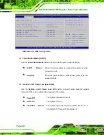
 IRQ10 

ƒ

 IRQ 

11 

ƒ

 IRQ 

14 

ƒ

 IRQ 

15 

Î


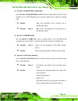
DMA Channel# [Available] 

Use the 

DMA Channel# 

option to assign a specific DMA channel to a particular PCI/PnP 

device. 

Î


Available D

EFAULT


The specified DMA is available to be used by 

PCI/PnP devices 

Î


Reserved  

The specified DMA is reserved for use by Legacy 

ISA devices 

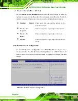
Available DMA Channels are: 

ƒ


DM Channel 0 

ƒ


DM Channel 1 

ƒ


DM Channel 3 

ƒ


DM Channel 5 

ƒ


DM Channel 6 

ƒ


DM Channel 7 

Summary of Contents for ICE-9602

Page 1: ...Basic Type 2 Module Page i IEI Technology Corp User Manual ICE 9652 9602 MODEL ICE 9652 9602 MODEL COM Express Basic Type 2 Module Intel Core 2 Duo Celeron M Processor with VGA LVDS GbE SATA USB and A...

Page 2: ...ICE 9652 9602 COM Express Basic Type 2 Module Page ii Revision Date Version Changes 5 March 2009 1 00 Initial release...

Page 3: ...tial damages arising out of the use or inability to use the product or documentation even if advised of the possibility of such damages This document contains proprietary information protected by copy...

Page 4: ...TATIC PRECAUTIONS 12 2 2 UNPACKING PRECAUTIONS 12 2 3 PACKING LIST 13 3 CONNECTORS 14 3 1 PERIPHERAL INTERFACE CONNECTORS 15 3 1 1 ICE 9652 9602 Layout 15 3 1 2 Peripheral Interface Connectors 16 3 2...

Page 5: ...Configuration 42 5 3 2 IDE Configuration 43 5 3 2 1 IDE Master IDE Slave 44 5 3 3 Floppy Configuration 49 5 3 4 Super IO Configuration 50 5 3 5 Win83627EHG Hardware Health Configuration 55 5 3 6 Win8...

Page 6: ...BIOS Setup 95 6 6 2 Driver Installation 95 6 7 INTEL MATRIX STORAGE MANAGER DRIVER INSTALLATION 101 6 8 IDE CONTROLLER INSTALLATION 105 6 9 ISMM INSTALLATION 115 A BIOS OPTIONS 121 B TERMINOLOGY 125...

Page 7: ...Connector 26 Figure 4 1 SO DIMM Installation 30 Figure 4 2 BIOS Selection Switch Location 32 Figure 4 3 LVDS Panel Resolution Selection Switch Location 33 Figure 4 4 PEG and SDVO Configuration Switch...

Page 8: ...d Starts 98 Figure 6 30 Preparing Setup Screen 99 Figure 6 31 InstallShield Wizard Welcome Screen 99 Figure 6 32 Audio Driver Software Configuration 100 Figure 6 33 Installation Wizard Updates the Sys...

Page 9: ...isk 114 Figure 6 53 iSMM Directory 115 Figure 6 54 iSMM Installation File 115 Figure 6 55 iSMM InstallShield Welcome Screen 116 Figure 6 56 iSMM License Agreement 116 Figure 6 57 iSMM Customer Informa...

Page 10: ...le 3 1 ICE 9652 9602 Interface Connectors 16 Table 3 2 COM Express Connector AB Pin Definitions 20 Table 3 3 COM Express Connector CD Pin Definitions 25 Table 3 4 SPI Flash Connector 26 Table 4 1 Jump...

Page 11: ...nfiguration 55 BIOS Menu 9 Hardware Health Configuration 56 BIOS Menu 10 Power 58 BIOS Menu 11 ACPI Configuration 59 BIOS Menu 12 APM Configuration 60 BIOS Menu 13 Remote Access Configuration 62 BIOS...

Page 12: ......

Page 13: ...ICE 9652 9602 COM Express Basic Type 2 Module Page 1 Chapter 1 1 Introduction...

Page 14: ...ovides multiple modern serial I O options while offering limited support for legacy I Os The COM Express standard allows the COM Express carrier board to be designed while leaving the choice of proces...

Page 15: ...sign compatibility Low cost product development 1 4 Features Some of the ICE 9652 9602 features are listed below Complies with PICMG COM Express specifications Complies with RoHS Embedded Intel Core 2...

Page 16: ...9652 9602 COM Express Basic Type 2 Module Page 4 1 5 Overview Picture An overview of the ICE 9652 9602 embedded module can be seen in Figure 1 2 and Figure 1 3 Figure 1 2 ICE 9652 9602 Overview Front...

Page 17: ...ICE 9652 9602 COM Express Basic Type 2 Module Page 5 Figure 1 3 ICE 9652 9602 Overview Reverse Side...

Page 18: ...ICE 9652 9602 COM Express Basic Type 2 Module Page 6 1 6 Dimensions The main dimensions of the ICE 9652 9602 are shown in the diagram below Length 125 mm Width 95 mm Figure 1 4 Main Dimensions mm...

Page 19: ...ICE 9652 9602 COM Express Basic Type 2 Module Page 7 1 6 1 Side Dimensions The figure below shows the dimensions as viewed from the side Figure 1 5 Side Dimensions mm...

Page 20: ...2 Module Page 8 1 7 Data Flow Figure 1 6 shows the data flow between the two on board chipsets and other components installed on the motherboard and described in the following sections of this chapte...

Page 21: ...a 533 MHz FSB Northbridge Chipset Intel GME965 GLE960 Southbridge Chipset Intel ICH8M E Memory ICE 9652 Two 200 pin 400 533 667 MHz DDR2 SO DIMM up to 4 0 GB ICE 9602 Two 200 pin 400 533 MHz DDR2 SO D...

Page 22: ...ower Specifications Power Support AT ATX power supported Power Consumption 12 V 3 039 A 2 2 GHz Intel Core 2 Duo T7500 processor with 1 0 GB DDR2 SO DIMM Operating Temperature 0 C 60 C 32 F 140 F Humi...

Page 23: ...ICE 9652 9602 COM Express Basic Type 2 Module Page 11 Chapter 2 2 Unpacking...

Page 24: ...ctrostatic discharge Self grounding Touch a grounded conductor every few minutes to discharge any excess static buildup Use an anti static pad When configuring any circuit board place it on an anti st...

Page 25: ...ontact the IEI reseller or vendor you purchased the ICE 9652 9602 from or contact an IEI sales representative directly To contact an IEI sales representative please send an email to sales iei com tw T...

Page 26: ...ICE 9652 9602 COM Express Basic Type 2 Module Page 14 Chapter 3 3 Connectors...

Page 27: ...eripheral Interface Connectors This chapter details all the jumpers and connectors 3 1 1 ICE 9652 9602 Layout The figures below show all the connectors and jumpers Figure 3 1 Connector and Jumper Loca...

Page 28: ...tor J2 SO DIMM socket SO DIMM socket DIMM1 SO DIMM socket SO DIMM socket DIMM2 SPI connector 6 pin wafer SPI1 Table 3 1 ICE 9652 9602 Interface Connectors 3 2 Internal Peripheral Connectors The sectio...

Page 29: ...A3 GBE0_MDI3 B3 LPC_FRAME A4 GBE0_LINK100 B4 LPC_AD0 A5 GBE0_LINK1000 B5 LPC_AD1 A6 GBE0_MDI2 B6 LPC_AD2 A7 GBE0_MDI2 B7 LPC_AD3 A8 GBE0_LINK B8 LPC_DRQ0 A9 GBE0_MDI1 B9 LPC_DRQ1 A10 GBE0_MDI1 B10 LP...

Page 30: ...WDT A28 ATA_ACT B28 AC_SDIN2 A29 AC_SYNC B29 AC_SDIN1 A30 AC_RST B30 AC_SDIN0 A31 GND B31 GND A32 AC_BITCLK B32 SPKR A33 AC_SDOUT B33 I2C_CK A34 BIOS_DISABLE B34 I2C_DAT A35 THRMTRIP B35 THRM A36 USB...

Page 31: ...CIE_RX3 A60 GND B60 GND A61 PCIE_TX2 B61 PCIE_RX2 A62 PCIE_TX2 B62 PCIE_RX2 A63 GPI1 B63 GPO3 A64 PCIE_TX1 B64 PCIE_RX1 A65 PCIE_TX1 B65 PCIE_RX1 A66 GND B66 WAKE0 A67 GPI2 B67 WAKE1 A68 PCIE_TX0 B68...

Page 32: ..._REF B89 VGA_RED A90 GND B90 GND A91 RSVD B91 VGA_GRN A92 RSVD B92 VGA_BLU A93 GPO0 B93 VGA_HSYNC A94 RSVD B94 VGA_VSYNC A95 RSVD B95 VGA_I2C_CK A96 GND B96 VGA_I2C_DAT A97 V12 B97 TV_DAC_A A98 V12 B9...

Page 33: ...Figure 3 4 CN Pinouts See Table 3 3 The standard COM Express connector locations and pinouts are shown below Figure 3 4 COM Express Connector CD Location Pin No Description Pin No Description C1 GND D...

Page 34: ...1 D19 PCI_GNT3 C20 PCI_GNT0 D20 PCI_REQ3 C21 GND D21 GND C22 PCI_REQ0 D22 PCI_AD1 C23 PCI_RESET D23 PCI_AD3 C24 PCI_AD0 D24 PCI_AD5 C25 PCI_AD2 D25 PCI_AD7 C26 PCI_AD4 D26 PCI_C BE0 C27 PCI_AD6 D27 PC...

Page 35: ...C48 PCI_AD31 D48 PCI_CLKRUN C49 PCI_IRQA D49 NC C50 PCI_IRQB D50 PCI_CLK C51 GND D51 GND C52 PEG_RX0 D52 PEG_TX0 C53 PEG_RX0 D53 PEG_TX0 C54 NC D54 NC C55 PEG_RX1 D55 PEG_TX1 C56 PEG_RX1 D56 PEG_TX1 C...

Page 36: ...D78 NC C79 NC D79 NC C80 GND D80 GND C81 NC D81 NC C82 NC D82 NC C83 NC D83 NC C84 GND D84 GND C85 NC D85 NC C86 NC D86 NC C87 GND D87 GND C88 NC D88 NC C89 NC D89 NC C90 GND D90 GND C91 NC D91 NC C9...

Page 37: ...D106 V12 C107 V12 D107 V12 C108 V12 D108 V12 C109 V12 D109 V12 C110 GND D110 GND Table 3 3 COM Express Connector CD Pin Definitions 3 2 3 SO DIMM Connector CN Label DIMM1 DIMM2 CN Type SO DIMM socket...

Page 38: ...r CN Label JSPI1 CN Type 6 pin wafer 1x6 CN Location See Figure 3 6 CN Pinouts See Table 3 4 The 6 pin SPI Flash connector is used to flash the BIOS Figure 3 6 SPI Flash Connector PIN DESCRIPTION 1 SP...

Page 39: ...ICE 9652 9602 COM Express Basic Type 2 Module Page 27 Chapter 4 4 Installation...

Page 40: ...static wristband can help to prevent ESD from damaging the board Self grounding Before handling the board touch any grounded conducting material During the time the board is handled frequently touch...

Page 41: ...D from the body and helps prevent ESD damage Place the ICE 9652 9602 on an antistatic pad o When installing or configuring the motherboard place it on an antistatic pad This helps to prevent potential...

Page 42: ...ith the socket The SO DIMM must be oriented in such a way that the notch in the middle of the SO DIMM must be aligned with the plastic bridge in the socket Step 3 Insert the SO DIMM Push the SO DIMM c...

Page 43: ...able 4 1 Jumpers 4 4 1 BIOS Selection Jumper Label SW1 Jumper Type 4 in 1 switch Jumper Settings See Table 4 2 Jumper Location See Figure 4 2 This jumper selects which BIOS to use There is a BIOS incl...

Page 44: ...e 4 3 Jumper Location See Figure 4 3 This switch sets the resolution of the panel attached to the LVDS output Settings are shown in Table 4 3 1 2 3 4 DESCRIPTION OFF OFF OFF OFF 640 x 480 18 bit ON OF...

Page 45: ...SW3 Jumper Type 4 in 1 switch Jumper Settings See Table 4 3 Jumper Location See Figure 4 4 This switch configures the PEG and SDVO settings Settings are shown in Table 4 3 Description Pin Pin Descrip...

Page 46: ...Location 4 5 Mounting the ICE 9652 9602 WARNING Never run the embedded module without an appropriate heat sink WARNING Please note that the installation instructions described in this manual should b...

Page 47: ...n order to prevent ESD damage to the CPU module and other electronic components like the CPU and SO DIMM module The ICE 9652 9602 embedded module has two standard COM Express connectors on the reverse...

Page 48: ...of the heatspreader are properly aligned with the corresponding holes on the COM Express module and baseboad Step 4 Align the heatsink Align the heatsink with the heatspreader Make sure the five reten...

Page 49: ...ICE 9652 9602 COM Express Basic Type 2 Module Page 37 Chapter 5 5 BIOS Setup...

Page 50: ...key is pressed restart the computer and try again 5 1 2 Using Setup Use the arrow keys to highlight items press ENTER to select use the PageUp and PageDown keys to change entries press F1 for help and...

Page 51: ...Changes If the computer cannot boot after changes to the system configuration is made CMOS defaults Use the jumper described in Chapter 5 5 1 5 BIOS Menu Bar The menu bar on top of the BIOS screen has...

Page 52: ...Select Screen Select Item Enter Go to SubScreen F1 General Help F10 Save and Exit ESC Exit v02 61 Copyright 1985 2006 American Megatrends Inc BIOS Menu 1 Main System Overview The System Overview lists...

Page 53: ...configure the CPU and peripheral devices through the following sub menus WARNING Setting the wrong values in the sections below may cause the system to malfunction Make sure that the settings made ar...

Page 54: ...Exit ESC Exit v02 61 Copyright 1985 2006 American Megatrends Inc BIOS Menu 2 Advanced 5 3 1 CPU Configuration Use the CPU Configuration menu BIOS Menu 3 to view detailed CPU specifications and configu...

Page 55: ...IDE Configuration Compatible Legacy IDE Channels SATA Pri PATA Sec Primary IDE Master Not Detected Primary IDE Slave Not Detected Secondary IDE Master Not Detected Secondary IDE Slave Not Detected Dis...

Page 56: ...hen entering setup BIOS auto detects the presence of IDE devices BIOS displays the status of the auto detected IDE devices The following IDE devices are detected and are shown in the IDE Configuration...

Page 57: ...The drive parameters are listed as follows Device Lists the device type e g hard disk CD ROM etc Type Indicates the type of devices a user can manually select Vendor Lists the device manufacturer Siz...

Page 58: ...specified channel CD DVD The CD DVD option specifies that an IDE CD ROM drive is attached to the specified IDE channel The BIOS does not attempt to search for other types of IDE disk drives on the spe...

Page 59: ...le I O mode program timing cycles between the IDE drive and the programmable IDE controller As the PIO mode increases the cycle time decreases Auto DEFAULT BIOS auto detects the PIO mode Use this valu...

Page 60: ...13 3 MB s MWDMA2 Multi Word DMA mode 2 selected with a maximum data transfer rate of 16 6 MB s UDMA0 Ultra DMA mode 0 selected with a maximum data transfer rate of 16 6 MB s UDMA1 Ultra DMA mode 1 sel...

Page 61: ...e the 32Bit Data Transfer BIOS option to enables or disable 32 bit data transfers Disabled Prevents the BIOS from using 32 bit data transfers Enabled DEFAULT Allows BIOS to use 32 bit data transfers o...

Page 62: ...4 Serial Port2 Address 2F8 IRQ3 Serial Port2 Mode Normal Parallel Port Address 378 Parallel Port Mode Normal Parallel Port IRQ IRQ7 Serial Port3 Address 3E8 Serial Port3 IRQ 11 Serial Port4 Address 2E...

Page 63: ...RQ3 DEFAULT Serial Port 2 I O port address is 3F8 and the interrupt address is IRQ3 3E8 IRQ4 Serial Port 2 I O port address is 3E8 and the interrupt address is IRQ4 2E8 IRQ3 Serial Port 2 I O port add...

Page 64: ...he EPP mode supports bi directional communication between the system and the parallel port device and the transmission rates between the two are much faster than the Normal mode ECP EPP The parallel p...

Page 65: ...to select the interrupt address for serial port 3 10 Serial port 3 IRQ address is 10 11 DEFAULT Serial port 3 IRQ address is 11 Serial Port4 Address 2E8 Use the Serial Port4 IRQ option to select the i...

Page 66: ...o select the interrupt address for serial port 5 10 Serial port 5 IRQ address is 10 11 DEFAULT Serial port 5 IRQ address is 11 Serial Port6 Address 2E0 Use the Serial Port6 IRQ option to select the in...

Page 67: ...YSFAN Speed N A CPUFAN Speed N A V3 3 3 376 V 12VIN 11 792 V VBAT 3 200 V SYSFAN PWM Control 250 CPUFAN PWM Control 250 PWM Duty Cycle Control Min 0 Max 225 Please input Dec number Select Screen Selec...

Page 68: ...voltages BIOS SETUP UTILITY Main Advanced PCIPNP Boot Security Chipset Power Exit On Chip Temperature 40 C 104 F CPU Temperature 38 C 100 F System Temperature 43 C 109 F SYSFAN2 Speed 3515 RPM Vore 1...

Page 69: ...voltages are monitored o Vcore o 3 30 Vin o VBAT o 5 00 Vin SYSFAN2 PWM Control 250 Use the SYSFAN2 PWM Control option to select PWM duty cycle control The PWM duty cycle specifies the width of the mo...

Page 70: ...Select Item Enter Go to SubScreen F1 General Help F10 Save and Exit ESC Exit v02 61 Copyright 1985 2006 American Megatrends Inc BIOS Menu 10 Power Power Type ATX Use the Power Type BIOS option to sele...

Page 71: ...nds Inc BIOS Menu 11 ACPI Configuration Suspend Mode S1 POS Use the Suspend Mode option to specify the sleep state the system enters when it is not being used S1 POS DEFAULT The system enters S1 POS s...

Page 72: ...t 1985 2006 American Megatrends Inc BIOS Menu 12 APM Configuration Power Button Mode On Off Use the Power Button Mode BIOS to specify how the power button functions On Off DEFAULT When the power butto...

Page 73: ...S option to enable activity on the PCI PME power management event controller to rouse the system from a suspend or standby state Disabled DEFAULT Wake event not generated by PCI PME controller activit...

Page 74: ...y activity on the mouse Enabled Wake event generated by activity on the keyboard or mouse 5 3 8 Remote Access Configuration Use the Remote Access Configuration menu BIOS Menu 13 to configure remote ac...

Page 75: ...rt Number COM1 Use the Serial Port Number option allows to select the serial port used for remote access COM1 DEFAULT System is remotely accessed through COM1 COM2 System is remotely accessed through...

Page 76: ...ng a terminal software and the slave Redirection After BIOS POST Always Use the Redirection After BIOS POST option to specify when console redirection should occur Disabled The console is not redirect...

Page 77: ...ller Mode HiSpeed Disabled Enabled Select Screen Select Item Enter Go to SubScreen F1 General Help F10 Save and Exit ESC Exit v02 61 Copyright 1985 2006 American Megatrends Inc BIOS Menu 14 USB Config...

Page 78: ...keyboard can control the system even when there is no USB driver loaded onto the system Disabled Legacy USB support disabled Enabled DEFAULT Legacy USB support enabled Auto Legacy USB support disabled...

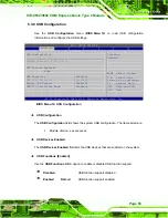
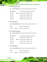
Page 79: ...A Channel 6 Available DMA Channel 7 Available Available Specified IRQ is available to be use the PCI PnP devices Reserved Specified IRQ is reserved for use by legacy ISA devices Select Screen Select I...

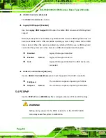
Page 80: ...option to assign a specific DMA channel to a particular PCI PnP device Available DEFAULT The specified DMA is available to be used by PCI PnP devices Reserved The specified DMA is reserved for use by...

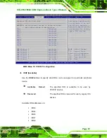
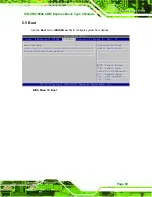
Page 81: ...t options BIOS SETUP UTILITY Main Advanced PCIPNP Boot Security Chipset Exit Boot Settings Boot Settings Configuration Configure settings during system boot Select Screen Select Item Enter Go to SubSc...

Page 82: ...will decrease the time needed to boot the system Select Screen Select Item Enter Go to SubScreen F1 General Help F10 Save and Exit ESC Exit v02 61 Copyright 1985 2006 American Megatrends Inc BIOS Men...

Page 83: ...ly To use the 10 keys on the keyboard press the Number Lock key located on the upper left hand corner of the 10 key pad The Number Lock LED on the keyboard lights up when the Number Lock is engaged On...

Page 84: ...American Megatrends Inc BIOS Menu 18 Security Change Supervisor Password Use the Change Supervisor Password to set or change a supervisor password The default for this option is Not Installed If a su...

Page 85: ...ay cause the system to malfunction BIOS SETUP UTILITY Main Advanced PCIPNP Boot Security Chipset Exit Advanced Chipset Settings WARNING Setting wrong values in below sections may cause system to malfu...

Page 86: ...et Configuration Memory Hole Disabled Use the Memory Hole option to reserve memory space between 15 MB and 16 MB for ISA expansion cards that require a specified area of memory to work properly If an...

Page 87: ...evice Enable 8 MB DEFAULT 8 MB of memory used by internal graphics device 5 7 1 1 Video Function Configuration Use the Video Function Configuration menu to configure the video device connected to the...

Page 88: ...ain Advanced PCIPNP Boot Security Chipset Power Exit Southbridge Chipset Configuration HDA Controller Enabled Spread Spectrum Mode Disabled Select Screen Select Item Enter Go to SubScreen F1 General H...

Page 89: ...8 Exit Use the Exit menu BIOS Menu 23 to load default BIOS values optimal failsafe values and to save configuration changes BIOS SETUP UTILITY Main Advanced PCIPNP Boot Security Chipset Exit Exit Opt...

Page 90: ...hanges option to discard the changes and remain in the BIOS configuration setup program Load Optimal Defaults Use the Load Optimal Defaults option to load the optimal default values for each of the pa...

Page 91: ...ICE 9652 9602 COM Express Basic Type 2 Module Page 79 Chapter 6 6 Software Installation...

Page 92: ...ed on the system 6 3 Chipset Driver Installation 82 6 4 VGA Driver Installation 85 6 5 LAN Driver Installation 89 6 6 Realtek HD Audio Driver ALC883 Installation 94 6 7 Intel Matrix Storage Manager Dr...

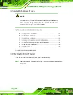
Page 93: ...COM Express Basic Type 2 Module Page 81 Step 7 The screen in Figure 6 1 appears Figure 6 1 Start Up Screen Step 8 Click ICE 9652 9602 Step 9 The list of drivers in Figure 6 2 appears S t e p 0 Figure...

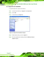
Page 94: ...following Step 1 Access the driver list shown in Figure 6 2 See Section 6 2 Step 2 Click 1 INF Step 3 A new window opens Figure 6 3 Figure 6 3 Chipset Driver Installation Program Step 4 Double click t...

Page 95: ...asic Type 2 Module Page 83 Figure 6 4 Chipset Driver Welcome Screen Step 6 Click NEXT to continue Step 7 The license agreement in Figure 6 5 appears Figure 6 5 Chipset Driver License Agreement Step 8...

Page 96: ...pt the license agreement and continue Step 10 The Read Me file in Figure 6 6 appears Figure 6 6 Chipset Driver Read Me File Step 11 Click NEXT in Figure 6 6 to start the driver installation Step 12 Af...

Page 97: ...nstallation Complete Step 13 Click FINISH to exit the InstallShield Wizard Step 0 6 4 VGA Driver Installation To install the VGA driver please do the following Step 1 Access the driver list shown in F...

Page 98: ...t the Operating System Step 4 Select the operating system from those shown in Figure 6 8 Step 5 A new window appears Figure 6 9 Figure 6 9 GMA Driver Step 6 Click the installation program icon in Figu...

Page 99: ...7 Figure 6 10 GMA Driver Readme File Step 8 Click NEXT to extract the GMA driver files See Figure 6 11 Step 9 The installation files are extracted See Figure 6 11 Figure 6 11 GMA Driver File Extractio...

Page 100: ...Welcome Screen Click NEXT to continue Step 11 The license agreement in Figure 6 13 appears Figure 6 13 GMA Driver License Agreement Step 12 Read the License Agreement Step 13 Click YES to accept the l...

Page 101: ...ars Figure 6 15 GMA Driver Installation Complete Step 16 Select Yes I want to restart the computer now and click FINISH See Figure 6 15 Step 0 6 5 LAN Driver Installation To install the chipset driver...

Page 102: ...Module Page 90 Figure 6 16 Access Windows Control Panel Step 4 Open the Realtek directory in Figure 6 16 Step 5 The screen in Figure 6 17 appears Figure 6 17 Double Click the System Icon Step 6 Open t...

Page 103: ...Type 2 Module Page 91 Step 7 The screen in Figure 6 18 appears Figure 6 18 Click the Device Manager Button Step 8 In Figure 6 18 select the operating system Step 9 The screen in Figure 6 19 appears F...

Page 104: ...ll directory shown in Figure 6 19 Step 11 The screen in Figure 6 20 appears Figure 6 20 PCIe Controller Driver Installation Icon Step 12 Double click the Setup icon in the screen in Figure 6 20 Step 1...

Page 105: ...ontinue Step 15 The Ready to Install screen in Figure 6 22 appears Figure 6 22 Ready to Install Step 16 Click NEXT to proceed with the installation Step 17 The program begins to install Step 18 The in...

Page 106: ...r installation is complete the screen in Figure 6 24 appears Figure 6 24 LAN Driver Installation Complete Step 20 Click FINISH to exit the InstallShield Wizard Figure 6 24 Step 0 6 6 Realtek HD Audio...

Page 107: ...up To do this reboot the system and press DEL during POST Step 2 Go to the Southbridge Configuration menu Enable the High Definition Audio controller Step 3 Press F10 to save the changes and exit the...

Page 108: ...ICE 9652 9602 COM Express Basic Type 2 Module Page 96 Figure 6 25 Select the Audio CODEC Step 3 Double click the ALC883 folder Step 4 Double click the appropriate operating system folder Figure 6 26...

Page 109: ...sic Type 2 Module Page 97 Figure 6 26 Select the OS Step 5 Double click the appropriate operating system version folder Figure 6 27 Figure 6 27 Select the OS Version Step 6 Double click the Setup exe...

Page 110: ...ge 98 Figure 6 28 Locate the Setup Program Icon Step 7 The InstallShield Wizard starts Figure 6 29 Figure 6 29 The InstallShield Wizard Starts Step 8 The InstallShield Wizard is prepared to guide the...

Page 111: ...Setup Screen Step 9 Once initialized the InstallShield Wizard welcome screen appears Figure 6 31 Figure 6 31 InstallShield Wizard Welcome Screen Step 10 Click NEXT to continue the installation Step 1...

Page 112: ...32 Audio Driver Software Configuration Step 12 The Installation Wizard updates the system as shown in Figure 6 33 Figure 6 33 Installation Wizard Updates the System Step 13 After the driver installati...

Page 113: ...FINISH to restart the computer Step 0 6 7 Intel Matrix Storage Manager Driver Installation To install the Intel Matrix Storage Manager driver please follow the steps below Step 1 Select 5 SATA from th...

Page 114: ...gure 6 35 InstallShield Wizard Setup Screen Step 4 Figure 6 36 shows the Matrix Storage Manager software configuring the installation process Figure 6 36 Matrix Storage Manager Setup Screen Step 5 Fig...

Page 115: ...ge Manager Welcome Screen Step 6 Click NEXT and a warning appears Figure 6 38 Read the warning carefully and decide whether or not to continue the installation process Figure 6 38 Matrix Storage Manag...

Page 116: ...e Agreement Step 8 Read the license agreement To accept the terms and conditions stipulated in the license agreement shown click YES and the Readme information file shown in Figure 6 40 appears Figure...

Page 117: ...rix Storage Manager Setup Complete Step 11 The confirmation screen offers the option of restarting the computer now or later For the settings to take effect the computer must be restarted Click FINISH...

Page 118: ...ICE 9652 9602 COM Express Basic Type 2 Module Page 106 Figure 6 42 Access Windows Control Panel...

Page 119: ...ICE 9652 9602 COM Express Basic Type 2 Module Page 107 Step 2 Double click the System icon Figure 6 43 Figure 6 43 Double Click the System Icon...

Page 120: ...ICE 9652 9602 COM Express Basic Type 2 Module Page 108 Step 3 Click the Device Manager button under the Hardware tab Figure 6 44 Figure 6 44 Click the Device Manager Button...

Page 121: ...A list of system hardware devices appears Figure 6 45 Figure 6 45 Device Manager List Step 5 The Device will be listed under Other Devices This means Windows does not recognize the device as an IDE De...

Page 122: ...ICE 9652 9602 COM Express Basic Type 2 Module Page 110 Step 7 The Device Driver Wizard appears Figure 6 46 Figure 6 46 Hardware Update Wizard Step 8 Select No not this time and click NEXT to continue...

Page 123: ...2 COM Express Basic Type 2 Module Page 111 Step 9 A new window Figure 6 47 appears Figure 6 47 Automatic or Manual Installation Step 10 Select Install from a list or specific location Advanced and the...

Page 124: ...press Basic Type 2 Module Page 112 Step 11 The Locate Driver Files window Figure 6 48 appears Figure 6 48 Select Driver Location Step 12 Select Don t search I will choose the driver to install and cli...

Page 125: ...Page 113 Step 13 The Select Driver Location window Figure 6 49 appears Figure 6 49 Select Driver Location Step 14 Click on Have Disk Step 15 The Install From Disk window Figure 6 50 appears Figure 6...

Page 126: ...The Locate File window Figure 6 51 appears Figure 6 51 Locate File Step 18 Choose the correct OS click on the latest driver and then click Open Step 19 The Install From Disk window Figure 6 52 appear...

Page 127: ...peratures or fan speeds rise above or fall below the set limits Step 1 Access the driver list shown in Figure 6 2 See Section 6 2 Step 2 Click 6 iSMM Step 3 The iSMM directory appears Figure 6 53 Figu...

Page 128: ...le Page 116 Step 7 The iSMM InstallShield Welcome Screen appears Figure 6 55 Figure 6 55 iSMM InstallShield Welcome Screen Step 8 Click NEXT to continue Step 9 The License Agreement screen appears Fig...

Page 129: ...Step 11 Click NEXT to continue Figure 6 56 Step 12 The Customer Information screen appears Figure 6 57 Figure 6 57 iSMM Customer Information Step 13 Fill in the User Name and Organization fields whic...

Page 130: ...52 9602 COM Express Basic Type 2 Module Page 118 Step 15 The Setup Type screen appears Figure 6 58 Figure 6 58 iSMM Setup Type Step 16 Select Complete Figure 6 58 Step 17 Click NEXT to continue Figure...

Page 131: ...COM Express Basic Type 2 Module Page 119 Step 18 The Installation Confirmation screen appears Figure 6 59 Figure 6 59 iSMM Installation Confirmation Step 19 Click INSTALL to begin installing the drive...

Page 132: ...hed installing Figure 6 60 Figure 6 60 iSMM InstallShield Wizard Complete Step 21 Click FINISH to exit the installation program Figure 6 60 Step 22 The Restart Confirmation screen appears Figure 6 61...

Page 133: ...ICE 9652 9602 COM Express Basic Type 2 Module Page 121 Appendix A A BIOS Options...

Page 134: ...o 47 PIO Mode Auto 47 DMA Mode Auto 47 S M A R T Auto 49 32Bit Data Transfer Enabled 49 Floppy A B 50 Serial Port1 Address 3F8 IRQ4 50 Serial Port2 Address 2F8 IRQ3 51 Serial Port2 Mode Normal 51 Para...

Page 135: ...64 Terminal Type ANSI 64 USB Configuration 65 USB Devices Enabled 65 USB Functions Enabled 65 USB 2 0 Controller Enabled 66 Legacy USB Support Enabled 66 USB2 0 Controller Mode HiSpeed 66 IRQ Availabl...

Page 136: ...ICE 9652 9602 COM Express Basic Type 2 Module Page 124 Discard Changes and Exit 78 Discard Changes 78 Load Optimal Defaults 78 Load Failsafe Defaults 78...

Page 137: ...ICE 9652 9602 COM Express Basic Type 2 Module Page 125 Appendix B B Terminology...

Page 138: ...represents a binary 0 while a high amplitude signal represents a binary 1 BIOS The Basic Input Output System BIOS is firmware that is first run when the computer is turned on and can be configured by...

Page 139: ...Intel SpeedStep Technology EIST allows users to modify the power consumption levels and processor performance through application software The application software changes the bus to core frequency r...

Page 140: ...for data transfers between storage devices and the computer chipsets The SATA bus has transfer speeds up to 1 5 Gbps and the SATA II bus has data transfer speeds of up to 3 0 Gbps S M A R T Self Moni...

Page 141: ...ICE 9652 9602 COM Express Basic Type 2 Module Page 129 Appendix C C Watchdog Timer...

Page 142: ...wn state A BIOS function call INT 15H is used to control the Watchdog Timer INT 15H AH 6FH Sub function AL 2 Sets the Watchdog Timer s period BL Time out value Its unit second is dependent on the item...

Page 143: ...herwise the system resets EXAMPLE PROGRAM INITIAL TIMER PERIOD COUNTER W_LOOP MOV AX 6F02H setting the time out value MOV BL 30 time out value is 48 seconds INT 15H ADD THE APPLICATION PROGRAM HERE CM...

Page 144: ...ICE 9652 9602 COM Express Basic Type 2 Module Page 132 Appendix D D Compatibility...

Page 145: ...ly run on the ICE 9652 9602 MS DOS 6 22 Microsoft Windows XP Professional with SP2 D 2 Compatible Processors The following Intel Socket P processors have been successfully tested on the ICE 9652 9602...

Page 146: ...urer Model No Capacity Speed Type Apacer 512MB SOD PC2 4300CL4 512MB 533MHz DDR2 Apacer 1GB SOD PC2 5300 CL5 1GB 667MHz DDR2 Apacer 2GB SOD PC2 6400 CL5 2GB 800MHz DDR2 Kingston KVR533D2S4 512 512MB 5...

Page 147: ...ICE 9652 9602 COM Express Basic Type 2 Module Page 135 Appendix E E Hazardous Materials Disclosure...

Page 148: ...wledges the presences of small quantities of certain materials in the product and is applicable to China RoHS only A label will be placed on each product to indicate the estimated Environmentally Frie...

Page 149: ...inted Circuit Board X O O O O X Metal Fasteners X O O O O O Cable Assembly X O O O O X Fan Assembly X O O O O X Power Supply Assemblies X O O O O X Battery O O O O O O O This toxic or hazardous substa...

Page 150: ...9602 COM Express Basic Type 2 Module Page 138 RoHS RoHS Pb Hg Cd CR VI PBB PBDE X O O O O X X O O O O X X O O O O X X O O O O O X O O O O X X O O O O X X O O O O X O O O O O O O SJ T11363 2006 X SJ T1...

Reviews: