ICE-BDE-T7 COM Express Module
Page 35
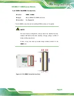
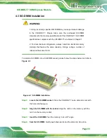
Figure 4-2: Connect the COM Express Connectors
Step 2:
Ensure a thermal pad is placed on the CPU of the ICE-BDE-T7.
Step 3:
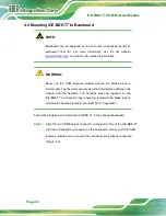
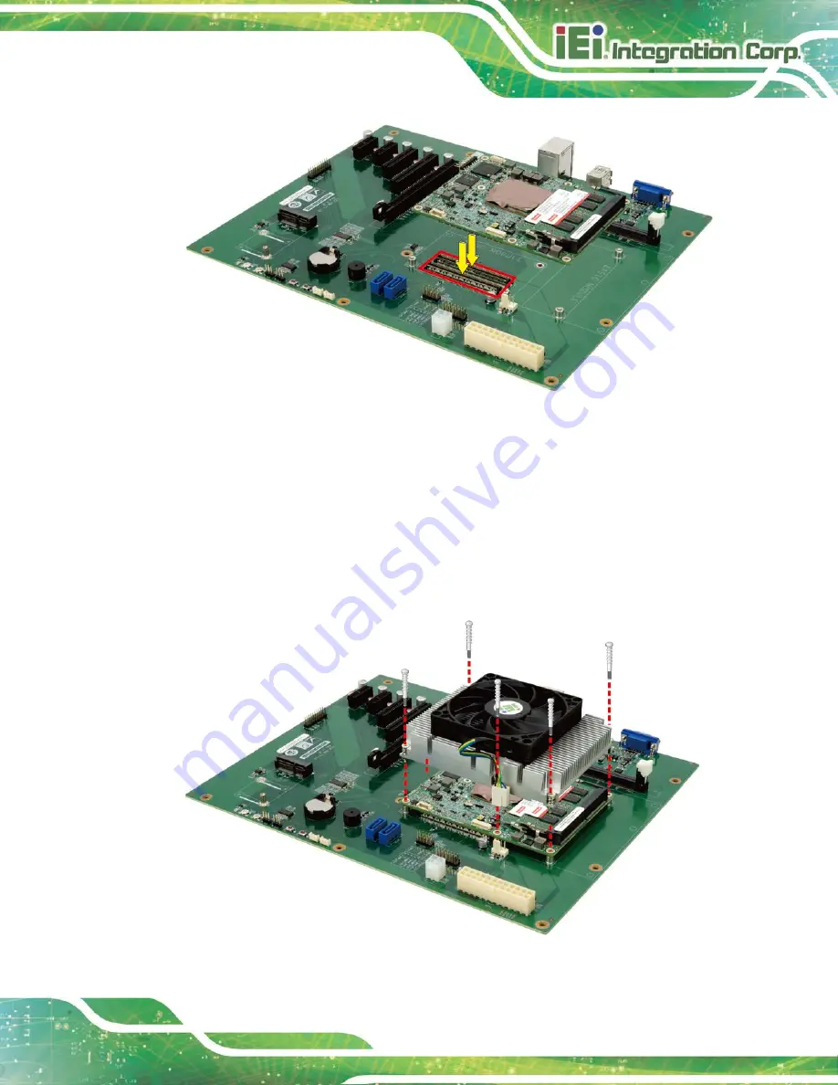
Place the heatsink on the ICE-BDE-T7, aligning the retention screw holes
Step 4:
Secure the heatsink to the ICE-BDE-T7 and the baseboard with the supplied
retention screws (Figure 4-3).
Figure 4-3: Secure the Heatsink
Summary of Contents for ICE-BDE-T7
Page 11: ...ICE BDE T7 COM Express Module Page 1 Chapter 1 1 Introduction...
Page 19: ...ICE BDE T7 COM Express Module Page 9 Chapter 2 2 Packing List...
Page 23: ...ICE BDE T7 COM Express Module Page 13 Chapter 3 3 Connectors...
Page 40: ...ICE BDE T7 COM Express Module Page 30 Chapter 4 4 Installation...
Page 46: ...ICE BDE T7 COM Express Module Page 36 Chapter 5 5 BIOS...
Page 81: ...ICE BDE T7 COM Express Module Page 71 6 Software Drivers Chapter 6...
Page 83: ...ICE BDE T7 COM Express Module Page 73 Appendix A A Regulatory Compliance...
Page 85: ...ICE BDE T7 COM Express Module Page 75 B Product Disposal Appendix B...
Page 87: ...ICE BDE T7 COM Express Module Page 77 Appendix C C BIOS Options...
Page 90: ...ICE BDE T7 COM Express Module Page 80 Appendix D D Digital I O Interface...
Page 93: ...ICE BDE T7 COM Express Module Page 83 Appendix E E Watchdog Timer...
Page 96: ...ICE BDE T7 COM Express Module Page 86 Appendix F F Hazardous Materials Disclosure...


