ICECARE-05 Pocket Mobile Field Assistant
Page 53
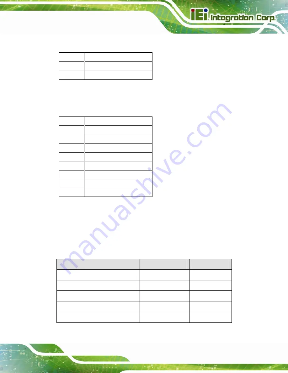
5.2.7 Speaker Connector (J2)
PIN NO.
DESCRIPTION
1 SPK_P
2 SPK_N
Table 5-8: Speaker Connector (J2) Pinouts
5.2.8 Touch Panel Connector (J6)
PIN NO.
DESCRIPTION
1 INT
2 RESET
3 SOMI
4 SIMO
5 CLK
6 CS0
7 VCC
8 GND
Table 5-9: Touch Panel Connector (J6) Pinouts
5.3 External Interface Panel Connectors
The table below lists the external interface panel connectors on the ICECARE-05
motherboard. Pinouts of these connectors can be found in the following sections.
Connector
Type
Label
Headset jack
Headset jack
J1
Power button
Push button
SW4
Reset button
Push button
SW3
microSD card slot
microSD card slot
CN1
Micro USB connector
Micro USB port
USB1
Table 5-10: External Interface Panel Connectors
Summary of Contents for ICECARE-05-ET-R10
Page 10: ...ICECARE 05 Pocket Mobile Field Assistant Page 1 Chapter 1 1 Introduction...
Page 18: ...ICECARE 05 Pocket Mobile Field Assistant Page 9 Chapter 2 2 Unpacking...
Page 21: ...ICECARE 05 Pocket Mobile Field Assistant Page 12 Chapter 3 3 Installation...
Page 28: ...ICECARE 05 Pocket Mobile Field Assistant Page 19 Chapter 4 4 Using the ICECARE 05...
Page 56: ...ICECARE 05 Pocket Mobile Field Assistant Page 47 Chapter 5 5 Interface Connectors...
Page 65: ...ICECARE 05 Pocket Mobile Field Assistant Page 56 Appendix A A Safety Precautions...
Page 70: ...ICECARE 05 Pocket Mobile Field Assistant Page 61 Appendix B B Hazardous Materials Disclosure...