IMBA-C2460 ATX Motherboard
Page 21
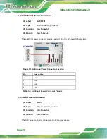
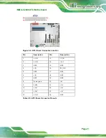
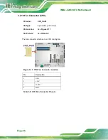
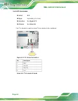
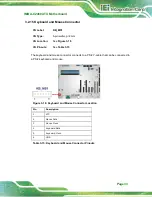
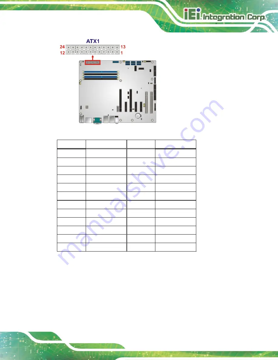
Figure 3-4: ATX Power Connector Location
Pin
Description
Pin
Description
1
+3.3V
13
+3.3V
2
+3.3V
14
-12V
3
GND
15
GND
4
+5V
16
PS_ON
5
GND
17
GND
6
+5V
18
GND
7
GND
19
GND
8
Power good
20
-5V
9
5VSB
21
+5V
10
+12V
22
+5V
11
+12V
23
+5V
12
+3.3V
24
GND
Table 3-5: ATX Power Connector Pinouts
Summary of Contents for IMBA-C2460
Page 15: ...IMBA C2460 ATX Motherboard Page 1 Chapter 1 1 Introduction...
Page 24: ...IMBA C2460 ATX Motherboard Page 10 Chapter 2 2 Packing List...
Page 29: ...IMBA C2460 ATX Motherboard Page 15 Chapter 3 3 Connectors...
Page 72: ...IMBA C2460 ATX Motherboard Page 58 Chapter 4 4 Installation...
Page 90: ...IMBA C2460 ATX Motherboard Page 76 Chapter 5 5 BIOS...
Page 134: ...IMBA C2460 ATX Motherboard Page 120 Appendix A A Regulatory Compliance...
Page 136: ...IMBA C2460 ATX Motherboard Page 122 B Product Disposal Appendix B...
Page 138: ...IMBA C2460 ATX Motherboard Page 124 Appendix C C BIOS Options...
Page 141: ...IMBA C2460 ATX Motherboard Page 127 Appendix D D Digital I O Interface...
Page 144: ...IMBA C2460 ATX Motherboard Page 130 Appendix E E Watchdog Timer...
Page 147: ...IMBA C2460 ATX Motherboard Page 133 Appendix F F Intel Matrix Storage Manager...
Page 151: ...IMBA C2460 ATX Motherboard Page 137 Appendix G G Error Beep Code...
Page 153: ...IMBA C2460 ATX Motherboard Page 139 Appendix H H Hazardous Materials Disclosure...

