321/20/2012164
P a g e 32
IMBA-G412IS A ATX Mo th e rb o a rd
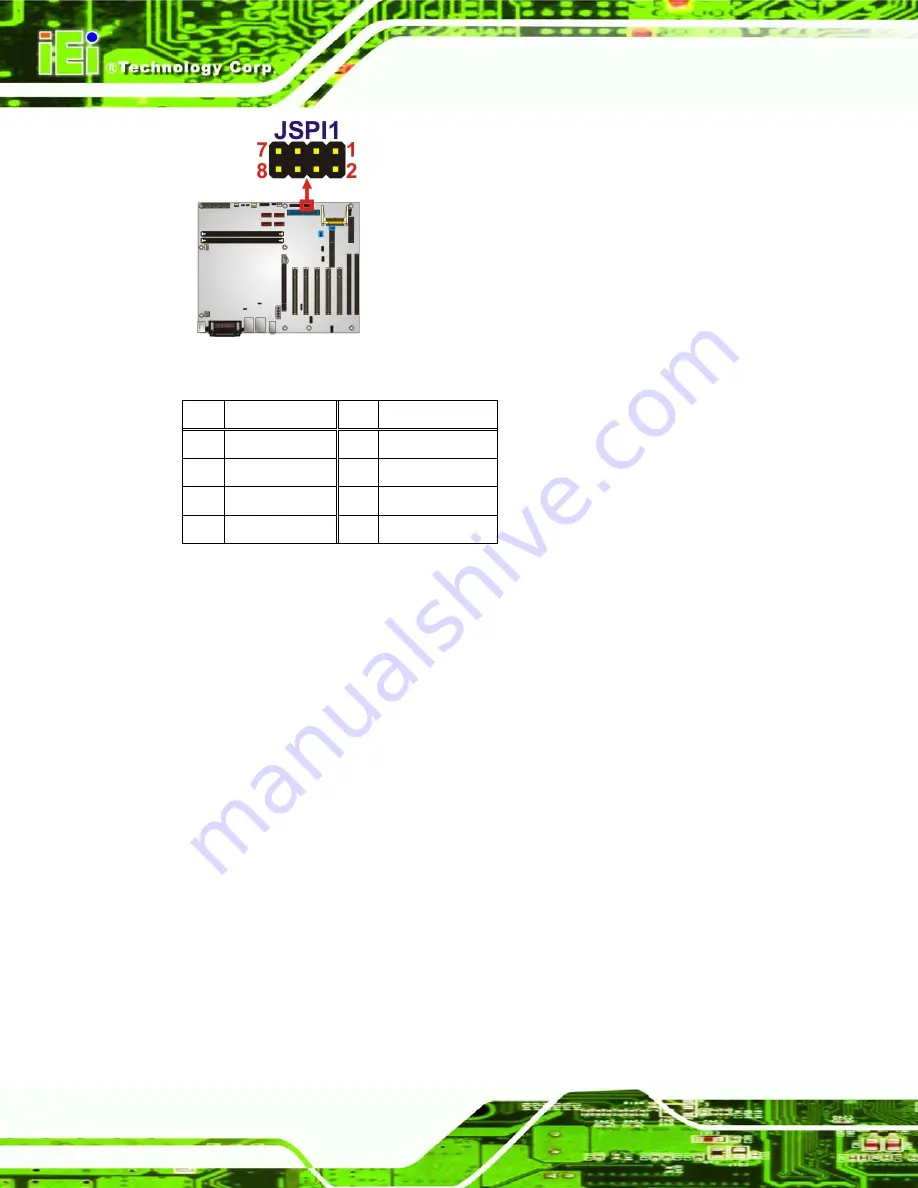
Figure 3-17: SPI Flash Connector
Pin
Description
Pin
Description
1
+3.3V
2
GND
3
CS#
4
CLOCK
5
SO
6
SI
7
NC
8
NC
Table 3-17: SPI Flash Connector
3.2.17
TP M Co n n e c to r
CN La b e l:
TP M1
CN Typ e :
20-pin header (2x10)
CN Lo c a tio n :
See
CN P in o u ts :
See
The Trusted Platform Module (TPM) connector secures the system on bootup.
Summary of Contents for IMBA-G412ISA-R20
Page 14: ......
Page 15: ...2012 1 202012 1 20 IMBA G412ISA ATX Motherboard Page 1 Chapter 1 1 Introduction...
Page 24: ...101 20 2012164 Page 10 IMBA G412ISA ATX Motherboard Chapter 2 2 Packing Lis t...
Page 29: ...2012 1 202012 1 20 IMBA G412ISA ATX Motherboard Page 15 Chapter 3 3 Connectors...
Page 55: ...2012 1 202012 1 20 IMBA G412ISA ATX Motherboard Page 41 Chapter 4 4 Ins tallation...
Page 80: ...661 20 2012164 Page 66 IMBA G412ISA ATX Motherboard Chapter 5 5 BIOS...
Page 120: ...1061 20 2012164 Page 106 IMBA G412ISA ATX Motherboard Appendix A A BIOS Options...
Page 124: ...1101 20 2012164 Page 110 IMBA G412ISA ATX Motherboard Appendix B B Terminology...
Page 128: ...1141 20 2012164 Page 114 IMBA G412ISA ATX Motherboard Appendix C C One Key Recovery...
Page 156: ...1421 20 2012164 Page 142 IMBA G412ISA ATX Motherboard Appendix D D Watchdog Timer...
Page 159: ...2012 1 202012 1 20 IMBA G412ISA ATX Motherboard Page 145 Appendix E E Digital I O Interface...


