IOVU-210AD-RK39 Panel PC
Page 23
NOTE:
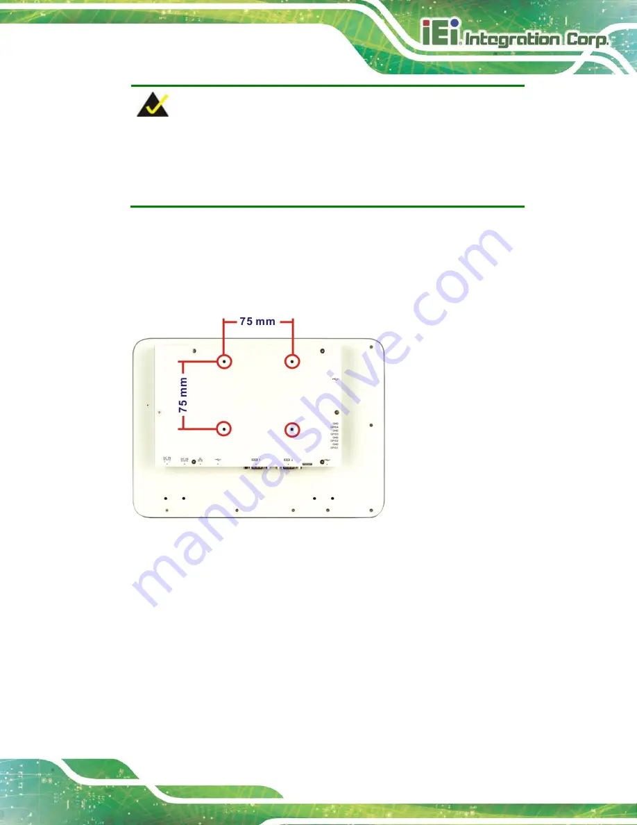
When purchasing the arm, please ensure that it is VESA compliant and that
the arm has a 75 mm interface pad. If the mounting arm is not VESA
compliant, it cannot be used to support the IOVU-210AD-RK39.
Step 2:
Once the mounting arm has been firmly attached to the surface, lift the
IOVU-210AD-RK39 onto the interface pad of the mounting arm.
Step 3:
Align the retention screw holes on the mounting arm interface with those in the
IOVU-210AD-RK39, as shown in
Figure 3-9: Arm Mounting Retention Screw Holes
Step 4:
Secure the IOVU-210AD-RK39 to the interface pad by inserting four retention
screws through the bottom of the mounting arm interface pad and into the
IOVU-210AD-RK39 (
).
Step 0:
Summary of Contents for IOVU-210AD-RK39
Page 9: ...IOVU 210AD RK39 Panel PC Page 1 Chapter 1 1 Introduction ...
Page 17: ...IOVU 210AD RK39 Panel PC Page 9 Chapter 2 2 Unpacking ...
Page 20: ...IOVU 210AD RK39 Panel PC Page 12 Chapter 3 3 Installation ...
Page 37: ...IOVU 210AD RK39 Panel PC Page 29 Chapter 4 4 Android OS ...
Page 45: ...IOVU 210AD RK39 Panel PC Page 37 Figure 4 8 Notification List and System Status ...
Page 46: ...IOVU 210AD RK39 Panel PC Page 38 Appendix A A Regulatory Compliance ...
Page 51: ...IOVU 210AD RK39 Panel PC Page 43 Appendix B B Safety Precautions ...
Page 56: ...IOVU 210AD RK39 Panel PC Page 48 Appendix C C Hazardous Materials Disclosure ...


