iSignager-300/300WL
Page 16
Step 2:
Once the mounting arm has been firmly attached to the surface, lift the
iSignager-300 onto the interface pad of the mounting arm.
Step 3:
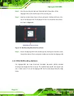
Align the retention screw holes on the mounting arm interface with those in the
rear of the iSignager-300. The iSignager-300 arm mount retention screw holes
are shown in
Figure 2-6: Arm Mounting Retention Screw Holes
Step 4:
Secure the iSignager-300 to the interface pad by inserting four retention screws
through the bottom of the mounting arm interface pad and into the iSignager-300.
Step 0:
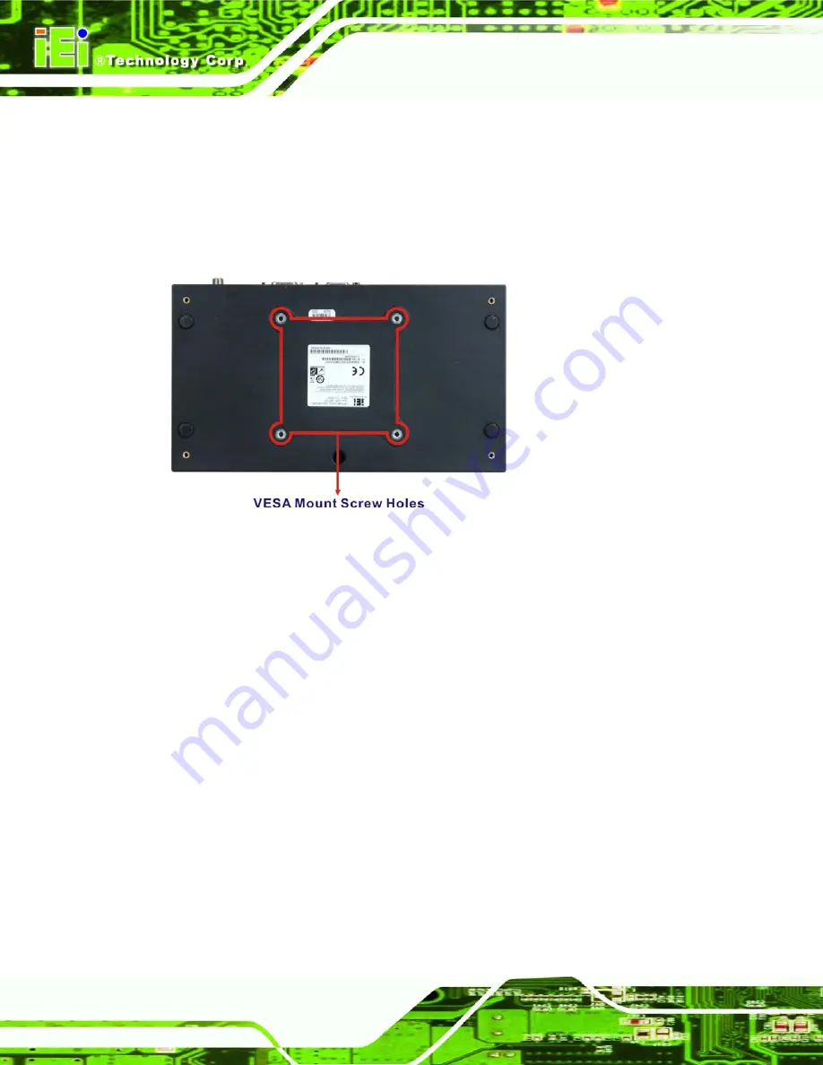
2.2.4 VESA Wall Mounting (Optional)
The iSignager-300 has Video Electronics Standards Association (VESA) standard
mounting holes tapped into the rear panel. The standard holes are M4 and support wall,
arm or stand mount. To mount the iSignager-300 onto the wall, please follow the steps
below.
Summary of Contents for Isignager-300
Page 2: ...iSignager 300 300WL Page ii Revision Date Version Changes 5 November 2009 1 00 Initial release...
Page 8: ......
Page 9: ...iSignager 300 Page 1 Chapter 1 1 Introduction...
Page 18: ...iSignager 300 300WL Page 10 Chapter 2 2 Installation...
Page 27: ...iSignager 300 Page 19 Appendix A A Check and Modify the Player Status...


