background image


iSignager-300/300WL

Page 12 


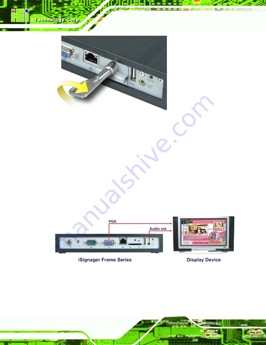
Figure 2-2: Lock the SD Slot Cover 


Step 3: 

Connect the player to the power adapter and connect the power adapter to the 

power source. 

Step 4: 

Connect the VGA cable to the VGA port of the iSignager-300. Then, connect the 

other side of the VGA cable to the display device. 

Step 5: 

Connect the audio cable to the audio output port on the bottom panel of the 

iSignager-300. Connect the other side of the audio cable to the audio input port 

of the display device.


Figure 2-3: Display Device Connection 


Summary of Contents for iSignager 300WL

Page 1: ...iSignager 300 Page i IEI Technology Corp User Manual iSignager 300 User Manual Digital Signage Player with LAN USB 2 0 VGA Audio Output Wireless LAN Rev 1 00 5 November 2009 MODEL iSignager 300 300WL ...

Page 2: ...iSignager 300 300WL Page ii Revision Date Version Changes 5 November 2009 1 00 Initial release ...

Page 3: ...ising out of the use or inability to use the product or documentation even if advised of the possibility of such damages This document contains proprietary information protected by copyright All rights are reserved No part of this manual may be reproduced by any mechanical electronic or other means in any form without prior written permission of the manufacturer TRADEMARKS All registered trademark...

Page 4: ...ESS FOR FRAME 9 1 10 SUPPORTED FORMATS 9 2 INSTALLATION 10 2 1 HARDWARE INSTALLATION 11 2 1 1 iSignager 300 Set Up 11 2 2 MOUNTING THE ISIGNAGER 300 13 2 2 1 Wall Mounting 13 2 2 2 Stand Mounting 15 2 2 3 Arm Mounting 15 2 2 4 VESA Wall Mounting Optional 16 A CHECK AND MODIFY THE PLAYER STATUS 19 A 1 CHECK AND MODIFY THE ISIGNAGER 300 STATUS BY SERIAL PORT 20 A 1 1 Successful Message LAN Connectio...

Page 5: ...iSignager 300 Page v A 2 2 1 PC 30 A 2 2 2 iSignager 300 30 A 3 ISIGNAGER 300WL SERIES NETWORK BEHAVIOR 31 ...

Page 6: ...ions millimeters 6 Figure 2 1 Insert SD Card 11 Figure 2 2 Lock the SD Slot Cover 12 Figure 2 3 Display Device Connection 12 Figure 2 4 Mounting Bracket Retention Screw Holes 14 Figure 2 5 Mounting Bracket Retention Screws 14 Figure 2 6 Arm Mounting Retention Screw Holes 16 Figure 2 7 Attach Wall Mounting Kit to the Wall 17 Figure 2 8 Hook Onto Wall Mounting Kit 17 Figure 2 9 Tighten Retention Scr...

Page 7: ...iSignager 300 Page vii List of Tables Table 1 1 iSignager 300 Model Variations 2 Table 1 2 iSignager 300 Specifications 7 Table 1 3 iSignager 300 Supported Formats 9 ...

Page 8: ......

Page 9: ...iSignager 300 Page 1 Chapter 1 1 Introduction ...

Page 10: ...lay sources anytime anywhere The iSignager 300 comes with an application software the iSignager AdExpress for Frame to help users to design and transfer dynamic contents for iSignager 300 With the iSignager 300 an advertising station is easily established and promotes the product and services in the simplest way Optional wireless connection enables the display sources to be updated anytime anywher...

Page 11: ...gement function Optional 802 11b g wireless module RoHS compliant 1 5 System Overview 1 5 1 Front View The power button of the iSignager 300 is located on the front panel Figure 1 1 shows the front view of the iSignager 300 Figure 1 1 iSignager 300 Front View 1 5 2 Rear Panel All peripheral device connectors are located on the rear panel of the iSignager 300 The following is a list of the rear pan...

Page 12: ...ASE T LAN for updating display content firmware and player settings via network interface SD card slot For installing SD card with media content created in the iSignager AdExpress for Frame USB connector For installing USB flash drive to update display content firmware and player settings Audio out jack Connects to audio input connector of the display device Reset button Resets the iSignager playe...

Page 13: ...5 1 5 3 Bottom View The bottom panel has few retention screw holes that support VESA MIS D 75 mounting and wall mounting brackets Figure 1 3 shows the bottom view of the iSignager 300 Figure 1 3 iSignager 300 Bottom View ...

Page 14: ...iSignager 300 300WL Page 6 1 6 Physical Dimensions The physical dimensions of the iSignager 300 are shown in Figure 1 4 Figure 1 4 iSignager 300 Physical Dimensions millimeters ...

Page 15: ...torage 1 x SD card slot Specs 2 0 Power Input Voltage 12 V DC input Power Adapter 40W 12VDC power adapter 100VAC 240VAC input 50 60Hz VESA Mounting MIS D 75 Dimension WxHxD mm 216 0 x 36 7 x 122 2 Construction Material ABS PC Plastic Operation Temperature 0 C 50 C Safety UL CUL CB BSMI EMC CE EMC FCC BSMI Table 1 2 iSignager 300 Specifications 1 8 Packing List The iSignager 300 is shipped with the...

Page 16: ... Page 8 1 AC power adaptor 1 Power cord 1 2GB SD card 1 SD slot cover 1 SD slot key 2 Wall mount brackets 1 Antenna iSignager 300WL only 1 iSignager AdExpress for Frame software companion CD 1 VESA wall mount kit optional ...

Page 17: ...300 supports many kinds of video audio and graphic formats The supported formats are listed in Table 1 3 iSignager 300 Supported Formats Video MJPEG Bit rate under 11000kbps MPEG1 Bit rate under 2500kbps MPEG2 Bit rate under 6000kbps H264 Bit rate under 12000kbps AVC Bit rate under 10000kbps XVID Bit rate under 6226kbps DIVX3 Bit rate under 8933kbps DIVX4 Bit rate under 5794kbps DIVX5 Bit rate und...

Page 18: ...iSignager 300 300WL Page 10 Chapter 2 2 Installation ...

Page 19: ...t a formatted SD card with display content and player settings generated by iSignager AdExpress for Frame into the SD card on the bottom panel Figure 2 1 Insert SD Card NOTE To remove the SD card just push the card in again When the card pops up remove it from the system Step 2 Place the SD slot cover to protect the SD card and lock it with the key ...

Page 20: ...ce Step 4 Connect the VGA cable to the VGA port of the iSignager 300 Then connect the other side of the VGA cable to the display device Step 5 Connect the audio cable to the audio output port on the bottom panel of the iSignager 300 Connect the other side of the audio cable to the audio input port of the display device Figure 2 3 Display Device Connection ...

Page 21: ...r 300 The iSignager 300 can be mounted on a wall stand or arm The mounting methods are described below CAUTION When mounting the iSignager 300 take care to tighten the retention screws or bolts until fully secure but do not over tighten Over tightening the retention screws or bolts may cause them to become stripped rendering them useless 2 2 1 Wall Mounting To mount the iSignager 300 onto a wall o...

Page 22: ...responding retention screw holes on the sides of the bottom surface Step 3 Secure the brackets to the system by inserting two retention screws into each bracket Figure 2 5 Mounting Bracket Retention Screws Step 4 Drill holes in the intended installation surface Step 5 Align the mounting holes in the sides of the mounting brackets with the predrilled ...

Page 23: ...with the screw holes on the stand mounting plate Step 2 Secure the iSignager 300 to the stand with the supplied retention screws Step 0 2 2 3 Arm Mounting The iSignager 300 is VESA Video Electronics Standards Association compliant and can be mounted on a VESA arm To mount the iSignager 300 on an arm please follow the steps below Step 1 The arm is a separately purchased item Please correctly mount ...

Page 24: ...re shown in Figure 2 6 Figure 2 6 Arm Mounting Retention Screw Holes Step 4 Secure the iSignager 300 to the interface pad by inserting four retention screws through the bottom of the mounting arm interface pad and into the iSignager 300 Step 0 2 2 4 VESA Wall Mounting Optional The iSignager 300 has Video Electronics Standards Association VESA standard mounting holes tapped into the rear panel The ...

Page 25: ...ded screws Make sure it is attached securely Figure 2 7 Attach Wall Mounting Kit to the Wall Step 2 Screw the mounting screws to the mounting holes on the rear of the iSignager 300 Step 3 Hook the iSignager 300 into the mounting holes on the wall mounting kit Figure 2 8 Hook Onto Wall Mounting Kit ...

Page 26: ...ge 18 Step 4 Tighten the top screw on the wall mounting kit to securely hold the iSignager 300 in place After this screw is tightened the iSignager 300 should not be able to move S t e p 0 Figure 2 9 Tighten Retention Screw ...

Page 27: ...iSignager 300 Page 19 Appendix A A Check and Modify the Player Status ...

Page 28: ...Port Follow the following steps and command to check and modify the iSignager 300 status by RS 232 serial port Step 1 In Windows XP Windows 2000 OS create a HyperTerminal session and prepare a null modem cable to connect the PC and the iSignager 300 Step 2 Modify COM1 Settings as below ...

Page 29: ...rinfo BINFMT_FLAT Loading file playerinfo Usage playerinfo i To display all information playerinfo sh hostname To change PC host name playerinfo ch hostname To change client host name playerinfo ddev val To change device type playerinfo si ip To change PC IP playerinfo ci ip To change client IP playerinfo d 1 0 To enable DHCP 1 or to disable DHCP 0 ...

Page 30: ...oading file new part1 bin playerinfo Information Romfs Version 107 Client Hostname Glob1 Client Ip eth0 10 10 19 253 Server Hostname RD VICKWU NB Server Ip 10 10 18 37 Display Device VGA 1024x768 60 Apps Version 106 WIFI BINFMT_FLAT Loading file new part1 bin playerinfo no wireless extensions Example 1 1 Use command playerinfo i and show the information of the player is connected via Wifi vick pla...

Page 31: ...system vick bin playerinfo sh RD VICKWU NB BINFMT_FLAT Loading file playerinfo Changing server hostname Done Example 3 Set client hostname to client system vick bin playerinfo ch vick BINFMT_FLAT Loading file playerinfo Changing client hostname Example 4 Set device display mode type vick bin playerinfo ddev VGA 1360x768 60 BINFMT_FLAT Loading file playerinfo Display Device VGA 1360x768 60 Example ...

Page 32: ...ning the systems IP address is 10 10 10 74 connecting to windows server windows server ip address is 10 10 10 58 windows server hostname is RD VICKWU NB connection Y CONNECTED TO WINDOWS SERVER gateway Unable to read gateway from interface Mac address of the board is 00 0b 6a 36 a3 10 Default gateway of the board is 0 0 0 0 Subnet mask is 255 255 254 0 Host name is vick DNS of the board is 172 16 ...

Page 33: ...te 17e02000 munmap of non mmaped memory by process 1812 play_animate 17e02000 killall play_rotate no process killed killall nano X no process killed killall audioplayer no process killed killall audio no process killed killall saver no process killed munmap of non mmaped memory by process 1806 banner 17e02000 munmap of non mmaped memory by process 1807 banner 17e02000 munmap of non mmaped memory b...

Page 34: ...stems ip address is 10 10 10 74 connecting to windows server windows server ip address is 10 10 10 58 windows server hostname is RD VICKWU NB connection Y CONNECTED TO WINDOWS SERVER Mac address of the board is 00 0b 6a 36 a3 10 Default gateway of the board is 10 10 10 1 Subnet mask is 255 255 254 0 Host name is vick DNS of the board is 172 16 2 6 00 0b 6a 36 a3 10 10 10 10 74 172 16 2 6 vick 10 1...

Page 35: ... g ifconfig eth0 broadcast 255 255 255 0 Step 7 Use the following command to modify Wifi settings Step 0 ifconfig ra0 IP set client IP value ifconfig ra0 netmask set client mask e g ifconfig ra0 netmask 192 168 1 255 ifconfig ra0 broadcast set client broadcast e g ifconfig ra0 broadcast 255 255 255 0 A 1 1 Successful Message LAN Connection If LAN is successfully connected the following messages ar...

Page 36: ...Mac address of the board is 00 9b 6b 36 a8 70 Default gateway of the board is 192 168 1 1 Subnet mask is 255 255 255 0 Host name is vick DNS of the board is 127 0 0 1 00 9b 6b 36 a8 70 192 168 1 10 127 0 0 1 vick 192 168 1 1 255 255 255 0 0 0 0 read returned 20 A 1 2 Successful Message Wifi Connection If Wifi is successfully connected the following messages are shown eth0 link down ra0 killall udh...

Page 37: ...d iwpriv ra0 set NetworkType infra Setting Authenticaion Mode Command iwpriv ra0 set AuthMode open Setting Encryption Type Command iwpriv ra0 set EncrypType WEP Setting Default Key ID Command iwpriv ra0 set DefaultKeyID 1 Setting Key Command iwpriv ra0 set Key1 1234567890abc 31 32 33 34 35 36 37 38 39 30 61 62 63 00 00 00 Setting SSID Command iwpriv ra0 set SSID iei_sw2 interface eth0 is Down inte...

Page 38: ... the LAN IP or WLAN IP e g ping 10 10 12 82 Press Enter If the reply message is shown the connection exists e g Reply from 10 10 12 82 bytes 32 time 10ms TTL 128 Reply from 10 10 12 82 bytes 32 time 10ms TTL 128 Reply from 10 10 12 82 bytes 32 time 10ms TTL 128 A 2 2 2 iSignager 300 To check if the specific IP connection exists in the client side check in a Hyper Terminal session of the iSignager ...

Page 39: ...r the iSignager 300WL Series takes LAN as the first priority by default when booting up If the LAN is successfully activated the iSignager 300WL Series does not activate the Wi Fi settings The Wi Fi settings are activated only when the LAN activation process is failed To setup the wireless connection please refer to the iSignager AdExpress for Frame user manual ...

Reviews: