background image


ITDB-100L Barcode Reader

Page 4 

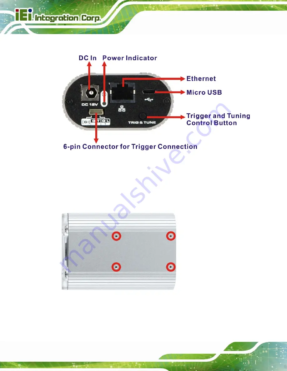
An overview of the rear panel is shown in 

6

Figure 1-3

 below. 

Figure 1-3: ITDB-100L Rear Panel 

1.3.3 Bottom Surface 

The bottom surface of the ITDB-100L contains four retention screw holes for the mounting 

bracket. 


Figure 1-4: ITDB-100L Bottom Surface 


Summary of Contents for ITDB-100L

Page 1: ...ITDB 100L Barcode Reader Page i User Manual MODEL ITDB 100L 2D Barcode Reader RoHS Compliant Rev 1 02 22 April 2014...

Page 2: ...s 22 April 2014 1 02 Updated Chapter 5 for the latest setup tool version 13 March 2014 1 01 Updated for the latest hardware specifications and application version Added Chapter 6 Configuring the ITDB...

Page 3: ...es arising out of the use or inability to use the product or documentation even if advised of the possibility of such damages This document contains proprietary information protected by copyright All...

Page 4: ...E 9 2 UNPACKING 10 2 1 ANTI STATIC PRECAUTIONS 11 2 2 UNPACKING PRECAUTIONS 11 2 3 UNPACKING CHECKLIST 12 3 INSTALLATION 14 3 1 INSTALLATION PRECAUTIONS 15 3 2 MOUNTING THE ITDB 100L 15 3 3 EXTERNAL P...

Page 5: ...Saved Images 45 5 7 SETTINGS MENU 47 5 8 NETWORK MENU 50 5 9 SECURITY MENU 51 5 10 FW UPGRADE AND BACKUP MODE 52 5 10 1 FW Upgrade Flow Chart 52 5 10 2 Upgrading the FW 53 5 10 3 Backup Mode 54 6 CONF...

Page 6: ...ges 67 6 6 2 Sending an Captured Image to IEI 68 A SAFETY PRECAUTIONS 70 A 1 SAFETY PRECAUTIONS 71 A 1 1 General Safety Precautions 71 A 1 2 Anti static Precautions 72 A 1 3 Product Disposal 73 A 2 MA...

Page 7: ...l Input Wiring 20 Figure 3 7 Digital Input and Output Connection 21 Figure 3 8 Ethernet Connection 22 Figure 3 9 Network Connection 23 Figure 3 10 Micro USB Connection 24 Figure 3 11 USB Standard Type...

Page 8: ...ining Mode Timer is Started 44 Figure 5 14 Trained Mode 45 Figure 5 15 Loading an Image 45 Figure 5 16 Loading Images 46 Figure 5 17 Settings 47 Figure 5 18 Symbology Settings 49 Figure 5 19 Network S...

Page 9: ...ITDB 100L Barcode Reader Page ix List of Tables Table 1 1 Technical Specifications 6 Table 3 1 Connector Pinouts 20 ITDB 100L...

Page 10: ...ITDB 100L Barcode Reader Page 1 Chapter 1 1 Introduction...

Page 11: ...for configuring the barcode reader and reading barcodes 1 2 Features The ITDB 100L features are listed below Image display Capture Preview Trigger modes One shot Serial shot Batch Presentation CMOS se...

Page 12: ...nation LEDs 1 x Lens An overview of the front panel is shown in Figure 1 26 Figure 1 2 ITDB 100L Front Panel 1 3 2 Rear Panel The ITDB 100L rear panel contains 1 x 6 pin connector for trigger connecti...

Page 13: ...view of the rear panel is shown in 6Figure 1 3 below Figure 1 3 ITDB 100L Rear Panel 1 3 3 Bottom Surface The bottom surface of the ITDB 100L contains four retention screw holes for the mounting brack...

Page 14: ...Code resolution 0 33 mm Reading distance at code resolution 50 mm 330 mm Illumination Element nm 2 x Red LEDs Visible red light 650 nm 660 nm I O Interfaces 1 x Micro USB port USB 2 0 data transmissio...

Page 15: ...fications Housing Die casting aluminum Housing color Silver Front cover Transparent plastic Weight 290 g without mounting bracket Dimensions LxWxH 89 8 mm x 62 mm x 32 mm Shock Resistance EN 60068 2 2...

Page 16: ...ITDB 100L Barcode Reader Page 7 1 5 Dimensions 1 5 1 ITDB 100L Dimensions Figure 1 5 ITDB 100L Dimensions millimeters...

Page 17: ...ITDB 100L Barcode Reader Page 8 1 5 2 Mounting Bracket Dimensions Figure 1 6 Mounting Bracket Dimensions millimeters...

Page 18: ...sfer to Database Built in Web Management USB Connection via API O X O X LAN Connection via API O X O X USB Keyboard Wedge HID X X X X Transfer to Database O O X X Built in Web Management X X X X O Com...

Page 19: ...ITDB 100L Barcode Reader Page 10 Chapter 2 2 Unpacking...

Page 20: ...wristband Wearing a simple anti static wristband can help to prevent ESD from damaging the board Self grounding Before handling the board touch any grounded conducting material During the time the bo...

Page 21: ...L from or contact an IEI sales representative directly To contact an IEI sales representative please send an email to sales ieiworld com The ITDB 100L is shipped with the following components Quantity...

Page 22: ...B 100L Barcode Reader Page 13 Quantity Item Image Standard 1 Mounting bracket P N 42110 0172C0 00 RS N 4 Mounting bracket screw P N 44045 020061 RS 1 Trigger connection cable 1 User manual and utility...

Page 23: ...ITDB 100L Barcode Reader Page 14 Chapter 3 3 Installation...

Page 24: ...Personnel The ITDB 100L must be installed and operated only by trained and qualified personnel Maintenance upgrades or repairs may only be carried out by qualified personnel who are familiar with the...

Page 25: ...DB 100L Step 2 Mount the ITDB 100L to an object with corresponding mounting screw for example a tripod Align the threaded hole on the mounting bracket with the mounting screw place the ITDB 100L over...

Page 26: ...ge 17 Figure 3 2 Mounting the ITDB 100L Step 3 To avoid reflection and glare from the scanned object and label surfaces it is recommended to mount the barcode reader at a 15 angle from vertical to the...

Page 27: ...ctions below 6 pin connector for trigger connection Ethernet Micro USB Power input 3 3 1 6 Pin Connector for Trigger Connection The 6 pin connector on the rear panel allows connection to an external t...

Page 28: ...e 6 pin plug Once aligned gently insert the trigger connection cable 6 pin plug into the 6 pin connector on the ITDB 100L Step 4 Connect the other end of the trigger connection cable to an external de...

Page 29: ...e Reader Page 20 Pin Color Signal 5 N A Reserved 6 N A Reserved Table 3 1 Connector Pinouts 3 3 1 1 Digital Output Wiring Figure 3 5 Digital Output Wiring 3 3 1 2 Digital Input Wiring Figure 3 6 Digit...

Page 30: ...100L Barcode Reader Page 21 3 3 1 3 Digital Input and Output Connection The below figure demonstrates a possible way of digital input and output connection Figure 3 7 Digital Input and Output Connect...

Page 31: ...et connector The location of the Ethernet connector is shown in Figure 1 3 Step 2 Align the connectors Align the Ethernet connector on the LAN cable with the Ethernet connector on the ITDB 100L See Fi...

Page 32: ...ITDB 100L Barcode Reader Page 23 3 3 2 1 Network Connection The below figure demonstrates a possible way of network connection Figure 3 9 Network Connection...

Page 33: ...connector is shown in Figure 1 3 Step 2 Align the Micro USB connectors Align the Micro USB connector on the Micro USB cable with the Micro USB connector on the ITDB 100L See Figure 3 10 Figure 3 10 Mi...

Page 34: ...PI opened the barcode data goes into the computer just as if it were being typed on a keyboard 3 3 4 Power Input Connector Step 1 Locate the power input connector The location of the power input conne...

Page 35: ...L Barcode Reader Page 26 3 4 Reading Distance and Field of View The following figure provides the supported reading distances and field of view for the ITDB 100L Figure 3 12 Reading Distance and Field...

Page 36: ...ITDB 100L Barcode Reader Page 27 Chapter 4 4 Driver and PC Setup Tool Installation...

Page 37: ...lation To install the device driver please follow the steps below Step 1 Connect the ITDB 100L to the computer and power supply A beep should be generated when the ITDB 100L is fed with power Step 2 G...

Page 38: ...dware Wizard appears Figure 4 2 Select No not this time then click Next to continue Figure 4 2 Found New Hardware Wizard Step 6 Select Install from a list or specific location then click Next to conti...

Page 39: ...o the system Step 8 Select Include this location in the search Figure 4 4 Step 9 Click Browse to select X directory in the Locate File window where X is the system CD drive Figure 4 4 Locate Driver Fi...

Page 40: ...DB 100L Barcode Reader Page 31 Figure 4 5 Driver Installation Step 12 When the driver installation is completed the following window appears Click Finish to exit Figure 4 6 Driver Installation Complet...

Page 41: ...Windows 7 32 bit and 64 bit Step 1 Ensure that the ITDB 100L is connected to the computer and power supply If the barcode reader cannot be recognized by the computer install the device driver Refer t...

Page 42: ...application installation Figure 4 8 Click Next to continue Figure 4 8 Select Installation Folder Step 6 The following screen appears Click Install to start the installation Figure 4 9 Ready for Insta...

Page 43: ...ITDB 100L Barcode Reader Page 34 Step 8 When the application installation is completed the following window appears Click Finish to exit Step 0 Figure 4 10 Installation Complete...

Page 44: ...ITDB 100L Barcode Reader Page 35 Chapter 5 5 Barcode Reader Setup Tool...

Page 45: ...t Microsoft Windows Vista 32 bit 64 bit Microsoft Windows 7 32 bit 64 bit 5 2 Launching the Setup Tool Step 1 Ensure that the ITDB 100L is connected to the computer and power supply A beep should be g...

Page 46: ...l appears Figure 5 2 Click Sync Settings Decode Now to enter the SETTING menu When using the setup tool for the first time refer to Section 5 4 Figure 5 2 Initial Screen 5 4 Initial Setting Step 1 Whe...

Page 47: ...Detecting the Available Connection Type Step 3 Click LAN or Micro USB depending on the connection type to the computer Figure 5 4 A confirmation dialog screen should appear Click OK to confirm the sel...

Page 48: ...tion page Figure 5 5 click Manual Setup to enter the SETTING menu to configure the barcode reader settings manually For automatic setup refer to Section 5 5 for details 5 5 Automatic Setup The user ma...

Page 49: ...Automatic setup is performed as shown in Figure 5 7 Figure 5 7 Automatic Setup Step 3 When the setup is complete the screen in Figure 5 8 appears Click NEXT to enter the VERIFICATION menu If automati...

Page 50: ...e 5 8 Setup Complete 5 6 Verification Menu In the VERIFICATION menu the user can set up the trigger behavior scanned result format and region of interest load scanned images and set a barcode image to...

Page 51: ...to trigger the ITDB 100L 5 6 1 Region of Interest The Region of Interest ROI item allows setting the scan area of the barcode reader Follow the steps below to use the ROI function Step 1 Click the ch...

Page 52: ...e and size Follow the steps below to set a barcode image to training mode Step 1 Click the Train Code item Figure 5 12 to start the training mode function The user can also press and hold the trigger...

Page 53: ...rted Step 3 The user has to click the Click And Train button Figure 5 13 to trigger the ITDB 100L within twelve seconds after the timer is started The user can also trigger the ITDB 100L by pressing t...

Page 54: ...ding Saved Images The user can load the saved images to view their detailed information When a scanned barcode is being saved it should be stored to the Save Image folder located at the same folder wh...

Page 55: ...To load all the images of a folder or selected images To load all the images of a folder or selected images click the icon indicated in Figure 5 16 and then select to load images by folder or by sele...

Page 56: ...Shot Serial Shot Batch or Presentation When setting to Serial Shot the ITDB 100L scans images continuously until an image is decoded successfully Decode result format The user can set the scanned resu...

Page 57: ...ection 5 6 2 for details TEST button Click the TEST button to scan a barcode by using the current settings SAVE button Click the SAVE button to save the current settings as a setting file LOAD button...

Page 58: ...ITDB 100L Barcode Reader Page 49 Figure 5 18 Symbology Settings...

Page 59: ...he barcode reader Figure 5 19 Network Setting Address Click DHCP to enable the DHCP function or set up the IP address mask and gateway manually Server IP Click Enable enter the server IP and then clic...

Page 60: ...ITDB 100L When a password is set the user has to enter the password before connecting to the barcode reader NOTE The default password is 1234 When setting to 1234 the user does not have to enter the p...

Page 61: ...d to restart 5 10 1 FW Upgrade Flow Chart Start The ITDB 100L restarts successfully and the FW is upgraded to the latest version Done Remove the power supply No Yes Reconnect the power supply and ente...

Page 62: ...from the menu Step 2 Click Path to locate the firmware file Step 3 Click Upgrade F W to start updating the firmware Figure 5 21 FW Upgrade Step 4 When the FW upgrade is complete the ITDB 100L restarts...

Page 63: ...he ITDB 100L is connected to the power supply press and hold the trigger and tuning control button Refer to Figure 1 3 for the location of the button Step 2 Connect the ITDB 100L to the power supply W...

Page 64: ...ITDB 100L Barcode Reader Page 55 Chapter 6 6 Configuring the ITDB 100L via an Android Device...

Page 65: ...urposes only 6 2 Installing and Launching the Android App NOTE It is recommended to install the app to the Android OS 4 1 2 and above To install and launch the Android app please follow the steps belo...

Page 66: ...ITDB 100L Barcode Reader Page 57 Step 2 When the app is installed the BarCode Reader icon will be shown on the application page Figure 6 2 Figure 6 2 App Icon Step 3 Tap the app icon to launch it...

Page 67: ...the captured image format and the maximum quantity of captured images Figure 6 3 When the settings are done tap OK to enter the barcode reader list screen Figure 6 3 Settings Menu Image Format Sets u...

Page 68: ...ess router is turned off To disable the DHCP Server function refer to the user manual of the wireless router The barcode reader list screen displays the ITDB 100L barcode readers found by the Android...

Page 69: ...r list screen the screen in Figure 6 5 will be shown Refer to the following subsections to configure the selected barcode reader so that a barcode image can be decoded successfully Figure 6 5 Decoding...

Page 70: ...ll be shown on the screen 6 5 3 Single Image Decoding Follow the steps below to proceed with single image decoding Step 1 Switch the capture mode icon to Step 2 Tap to start single image decoding Step...

Page 71: ...ontrol button Refer to Section 5 6 2 for details Step 1 Tap to start the training mode function Step 2 Four beeps are being generated the illumination LEDs start to flash and the training mode button...

Page 72: ...eter Settings 6 5 6 1 Automatic Setting The automatic option allows the barcode reader to adjust to its optimal settings according to the barcode reading environment Step 1 Tap to start automatic sett...

Page 73: ...stop Then all the parameters will be restored to the last saved settings 6 5 6 2 LED Brightness The LED brightness option allows the user to adjust the LED brightness Step 1 Tap then drag the slider...

Page 74: ...adjust the exposure time Figure 6 8 Exposure Time Step 2 Tap or the Back key on the Android device to return to the barcode reader list screen Then the exposure time parameter will be stored to the b...

Page 75: ...code reader list screen Then the gain parameter will be stored to the barcode reader 6 5 6 5 Decoding Time The user may need to increase the decoding time when the scanned barcode is complicated or th...

Page 76: ...tored to the barcode reader 6 6 Checking the Decoded Images The parameter values of each captured image are displayed below the image Figure 6 11 6 6 1 Checking Captured Images Follow the steps below...

Page 77: ...r values The parameter values of each captured image are displayed below the image Figure 6 11 Figure 6 11 Parameter Values 6 6 2 Sending an Captured Image to IEI The user might need to report a faile...

Page 78: ...ITDB 100L Barcode Reader Page 69 Step 1 Repeat Step 1 Step 4 in previous section Step 2 Tap the image to bring up the toolbar Step 3 Tap Share then select e mail to send the selected image to IEI...

Page 79: ...ITDB 100L Barcode Reader Page 70 Appendix A A Safety Precautions...

Page 80: ...when moving installing or modifying the system Do not apply voltage levels that exceed the specified voltage range Doing so may cause fire and or an electrical shock Electric shocks can occur if open...

Page 81: ...ing anti static precautions are strictly adhered to Wear an anti static wristband Wearing a simple anti static wristband can help to prevent ESD from damaging any electrical component Self grounding B...

Page 82: ...t must be disposed of separately from normal household waste This includes monitors and electrical accessories such as signal cables or power cords When you need to dispose of your display products pl...

Page 83: ...list of items to use when cleaning the ITDB 100L Cloth Although paper towels or tissues can be used a soft clean piece of cloth is recommended when cleaning the ITDB 100L Water or rubbing alcohol A cl...

Page 84: ...ITDB 100L Barcode Reader Page 75 Appendix B B Hazardous Materials Disclosure...

Page 85: ...presences of small quantities of certain materials in the product and is applicable to China RoHS only A label will be placed on each product to indicate the estimated Environmentally Friendly Use Pe...

Page 86: ...it Board O O O O O O Metal Fasteners O O O O O O Cable Assembly O O O O O O Fan Assembly O O O O O O Power Supply Assemblies O O O O O O Battery O O O O O O O This toxic or hazardous substance is cont...

Page 87: ...ITDB 100L Barcode Reader Page 78 RoHS RoHS Pb Hg Cd CR VI PBB PBDE O O O O O O O O O O O O O O O O O O O O O O O O O O O O O O O O O O O O O O O O O O O O O O O O O SJ T11363 2006 X SJ T11363 2006...

Reviews: