IVS-200-ULT2 Embedded System
Page 79
6.1 Peripheral Interface Connectors
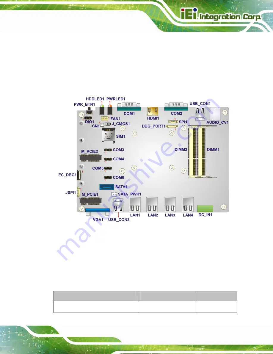
The IVS-200-ULT2 embedded system motherboard comes with a number of peripheral
interface connectors and configuration jumpers. The connector locations are shown in
5
. The Pin 1 locations of the on-board connectors are also indicated in the
diagram below. The connector pinouts for these connectors are listed in the following
sections.
Figure 6-1: Jumper and Connector Locations
6.2 Internal Peripheral Connectors
Internal peripheral connectors are found on the motherboard and are only accessible
when the motherboard is outside of the chassis. The table below shows a list of the
peripheral interface connectors on the IVS-200-ULT2’s motherboard. Pinouts of these
connectors can be found in the following sections.
Connector
Type
Label
Battery connector
2-pin wafer
CN1
Summary of Contents for IVS-200-ULT2
Page 13: ...IVS 200 ULT2 Embedded System Page 1 Chapter 1 1 Introduction ...
Page 22: ...IVS 200 ULT2 Embedded System Page 10 Chapter 2 2 Unpacking ...
Page 25: ...IVS 200 ULT2 Embedded System Page 13 VESA MIS D 100 wall mount kit Table 2 2 Optional Items ...
Page 26: ...IVS 200 ULT2 Embedded System Page 14 Chapter 3 3 Installation ...
Page 50: ...IVS 200 ULT2 Embedded System Page 38 Chapter 4 4 BIOS ...
Page 85: ...IVS 200 ULT2 Embedded System Page 73 Chapter 5 5 Troubleshooting and Maintenance ...
Page 90: ...IVS 200 ULT2 Embedded System Page 78 Chapter 6 6 Interface Connectors ...
Page 97: ...IVS 200 ULT2 Embedded System Page 85 Appendix A A Regulatory Compliance ...
Page 102: ...IVS 200 ULT2 Embedded System Page 90 B Safety Precautions Appendix B ...
Page 108: ...IVS 200 ULT2 Embedded System Page 96 Appendix C C BIOS Menu Options ...
Page 111: ...IVS 200 ULT2 Embedded System Page 99 Appendix D D Watchdog Timer ...
Page 114: ...IVS 200 ULT2 Embedded System Page 102 Appendix E E Hazardous Materials Disclosure ...


